NVIDIA Jetson TX2/TX2i OEM Product Design Guide
JETSON TX2/TX2i OEM PRODUCT | DESIGN GUIDE | 20180618 15
Figure 7. VIN_PWR_BAD# Detection Test Circuit for Uncontrolled Power-down Case
VIN_PWR_BAD#
VDD_IN
~20%
droop
Voltage measured at
USB0_OTG_ID pin
2.9V
>20ms
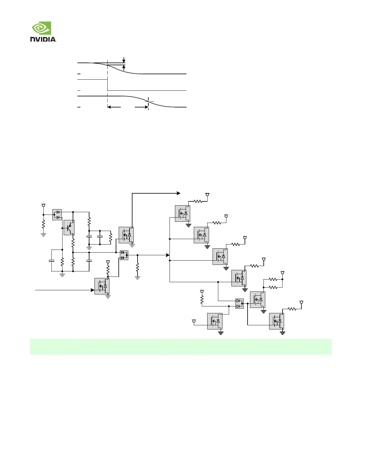
3.4 Power Discharge
In order to meet the Pow er Dow n requirements, discharge circuitry is required. In the figure below the DISCHARGE signal is
generated, based on a transition of the CARRIER_POWER_ON signal or the removal of the main supply (VDD_MUX/V DD_IN).
When DISCHARGE is asserted, VDD_5V0_IO_SYS, VDD_3V3_SYS, VDD_1V8 and VDD_3V3_SLP are forced to GND in a
controlled manner. Removal of the VDD_MUX supply also causes VIN_PWR_BAD# to go active w hich causes the module to
initiate a controlled shut dow n.
Figure 8. Power Discharge
VDD_MUX
10uF
1uF
G
S
D
10k
10uF
10k
10M
0
100k
DISCHARGE
VIN_PWR_BAD#
(Jetson Module Pin B8)
47k
VDD_MUX
CARRIER_PWR_ON
(Jetson Module pin A48)
BAT54ALT1
BAT54CW
MMBT
4403
NTR4003
NT1G
NTR4001
NT1G
E
B
C
G
S
D
4.7uF
Tol.
100k
100k
G
S
D
G
S
D
G
S
D
G
S
D
G
S
D
G
S
D
100
VDD_5V0_IO_SYS
47
VDD_3V3_SYS
36
VDD_1V8
47
VDD_3V3_SLP
NTR4003
NT1G
NTR4003
NT1G
NTR4003
NT1G
NTR4003
NT1G
VDD_12V_SLP
VDD_5V0_IO_SLP
100
G
S
D
470
FDV301N
NTR4003
NT1G
NTR4003
NT1G
BAT54CW
470
75k
VDD_3V3_SLP
VDD_5V0_IO_SYS
The figure above is based on the carrier board reference design. Refer to the latest carrier board reference design
(P2597_B04 or later) for details.
3.5 Module Power-on Type Detection & Control
The follow ing describes w hat is required in a carrier board design to support Jetson TX2 and Jetson TX2i in a design that
requires a pow er button press to pow er the system on. If a design requires the system to pow er on immediately after the main
pow er supply is connected/enabled, see the “Optional Auto-Pow er-On Support” section.
Jetson TX2i uses a different PMIC (MAX20024) than Jetson TX2 (MAX77620). Due to the PMIC architecture differences, if the
platform requires a button press, the Pow er-on mechanism w ill need to change, from Edge to level triggered. This w ill require
the carrier boards to detect w hether a Jetson TX2 module or Jetson TX2i module is installed. A Reserved pin on the connector
 Loading...