NVIDIA Jetson TX2/TX2i OEM Product Design Guide
JETSON TX2/TX2i OEM PRODUCT | DESIGN GUIDE | 20180618 73
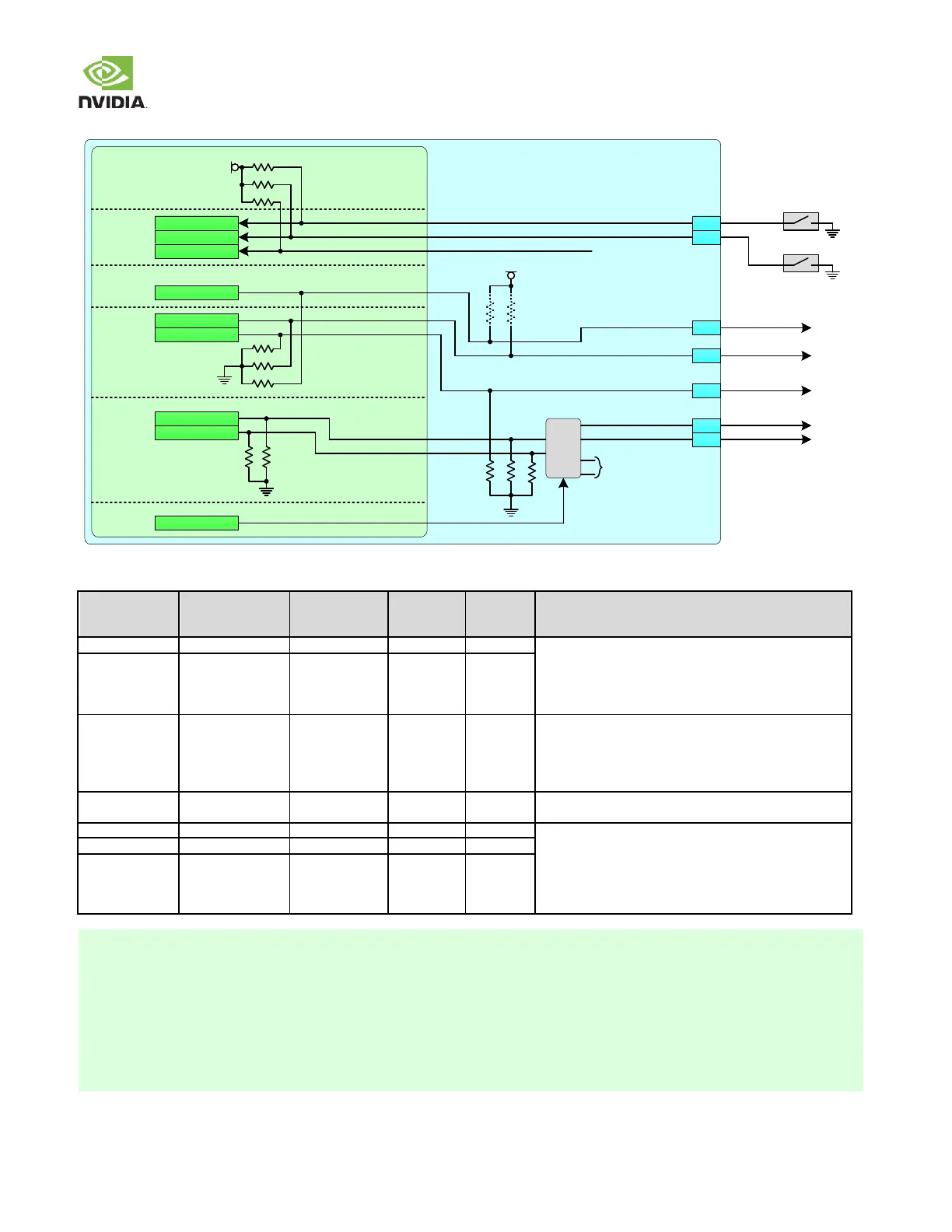
Figure 46. Strap Connections
Jetson TX2/TX2i
Tegra
AO
UART7_TX
CONN
UART4_TX
UART3_TX
UART1_RTS_N
DEBUG
4.7kΩ
4.7kΩ
4.7kΩ
1.8V
4.7kΩ
4.7kΩ
SYS
GPIO_SW1
~100kΩ
1.8V
~100kΩ
~100kΩ
GPIO_SW2
GPIO_SW4
~100kΩ
~100kΩ
~100kΩ
~100kΩ
~100kΩ
UART4_RTS_N
RCM0 Strap
RCM1 Strap
RCM2 Strap
RAM_CODE0 Strap
RAM_CODE1 Strap
BOOT_SELECT2 Strap
BOOT_SELECT1 Strap
BOOT_SELECT0 Strap
E1
E2
G11
D9
D8
H10
G10
FORCE_RECOV#
SLEEP#
UART0_RTS
UART1_TX
UART7_TX
UART3_TX
UART3_RTS
BT Wake AP
(On-Module
Bt/Wi-Fi TX2 only)
Mux
SEL
UART
(On-Module
Bt/Wi-Fi TX2 only)
SPI
QSPI_IO2
RECOVERY
VOL DN / SLEEP
(See Note)
Table 86. Power-on Strapping Breakdown
Recovery Mode [1:0]
x1: Normal boot from secondary device
10: Forced Recovery Mode
00: Reserved
See critical warning in note 1
[3:2] Selects secondary boot device configuration set
within the BCT. For Nvidia use only.
[1:0] Selects DRAM configuration set within the BCT. For
Nvidia use only.
See critical warning in Note 2.
Software reads value and determines Boot device to be
configured and used
000 = eMMC x8 BootModeOFF, 512-byte page. Maps to
SDMMC w/config=0x0001 size. 26MHz
001 111 Reserved
See Note 3 & 5. See critical warning in Note 4.
1. If the SLEEP# pin is used in a design, it must not be driven or pulled low during power-on at the same time as
FORCE_RECOV# is pulled low for Recovery Mode as this would change the strapping and select a reserved mode.
Violating this requirement will prevent the system from entering Recovery Mode.
2. If UART1_TX or UART0_RTS are used in a design, they must not be driven or pulled high or low during power-on.
Violating this requirement can change the RAM_CODE strapping & result in functional failures.
3. The above BOOT_SELECT option is only in effect in "regular boot" conditions i.e. coldboot. If "Forced Recovery" mode is
detected (FORCE_RECOV# low at boot), that mode take precedence over the eMMC boot device choice.
4. If UART7_TX (on RSVD pin) is used in a design, it must not be driven or pulled high during power-on as this would affect
the BOOT_SELECT strapping. Violating this requirement will likely prevent the system from booting.
 Loading...