JX Quick Start Guide 9
INSTALLATION
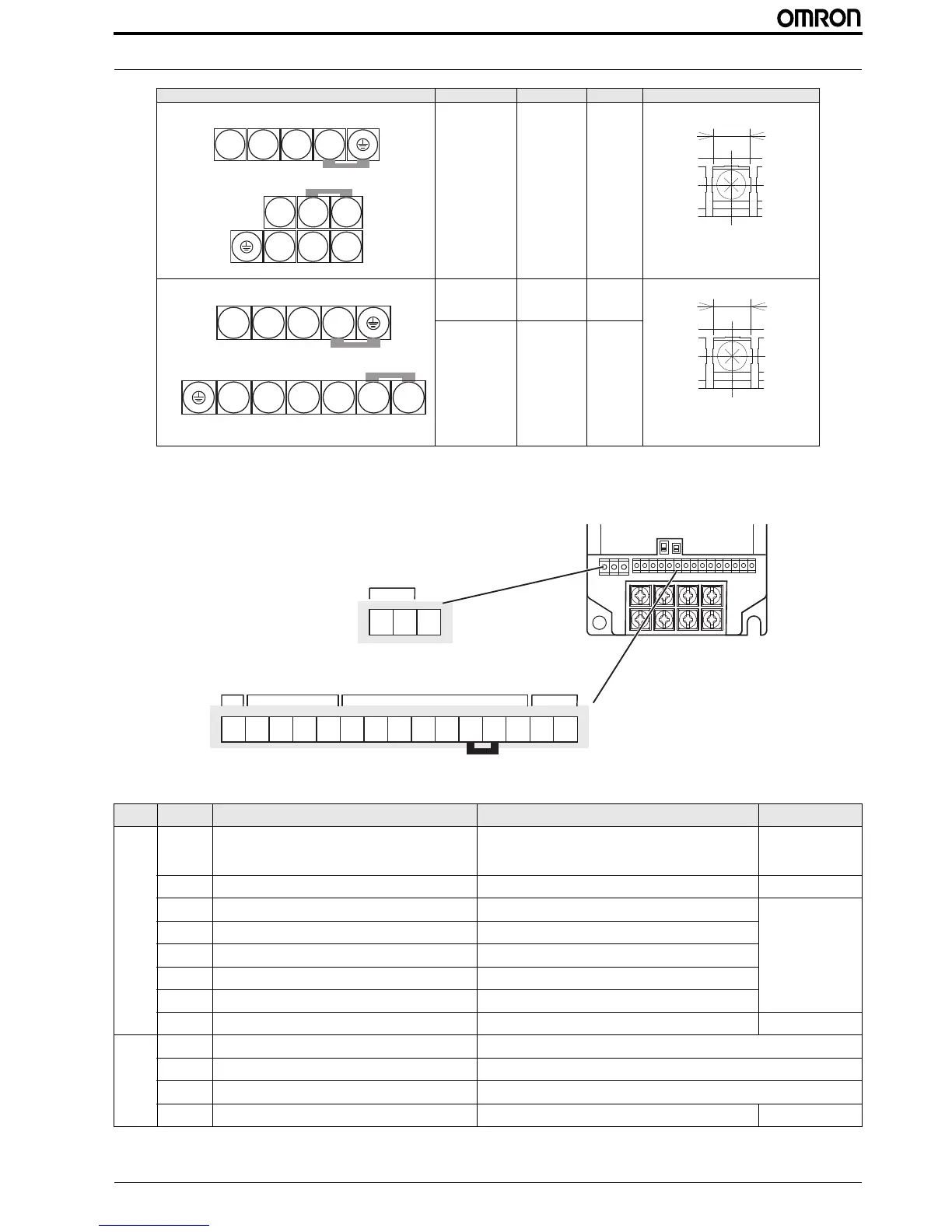
*1. For 3G3JX-AB, R/L1 corresponds to L1 and T/L3 to N, terminal S/L2 is not available. Connect a single-phase 200 VAC input to terminals L1 and N.
2.6 Control wiring
Main circuit terminal block Model (3G3JX-) Screw size W (mm)
AB002 to AB004
A2002 to A2007
*1
M3.5 7.1
A2015 to A2037
A4004 to A4040
AB007 to AB022
*1
M4 9.2
A2055 to A2075
A4055 to A4075
M5 13
Type No. Signal name Function Signal level
Digital
input
signals
PCS
Input power supply
External power supply terminal for input signal (input)
...At sink logic
Internal power supply output terminal for input signal (output)
...At source logic
24 VDC ±10%
P24
Internal 24 VDC 24 VDC internal power supply 24 VDC ±10%, 100 mA
1
Multi-function input selection 1 Factory setting: Forward/Stop
27 VAC max
ON voltage: 18 V min
OFF voltage: 3 V max
Load current: 5 mA
Min ON time: 12 ms
2
Multi-function input selection 2 Factory setting: Reverse/Stop
3
Multi-function input selection 3 Factory setting: Fault reset
4
Multi-function input selection 4 Factory setting: Emergency stop fault
5
Multi-function input selection 5 Factory setting: Multi-step speed reference 1
L
Multi-function input selection common
Analog
input
signals
H
Frequency reference power supply 10 VDC 10 mA max
O
Voltage frequency reference signal 0 to 10 VDC (10 k)
OI
Current frequency reference signal 4 to 20 mA (250 )
L
Frequency reference common

 Loading...


