JX Quick Start Guide 19
PROGRAMMING JX
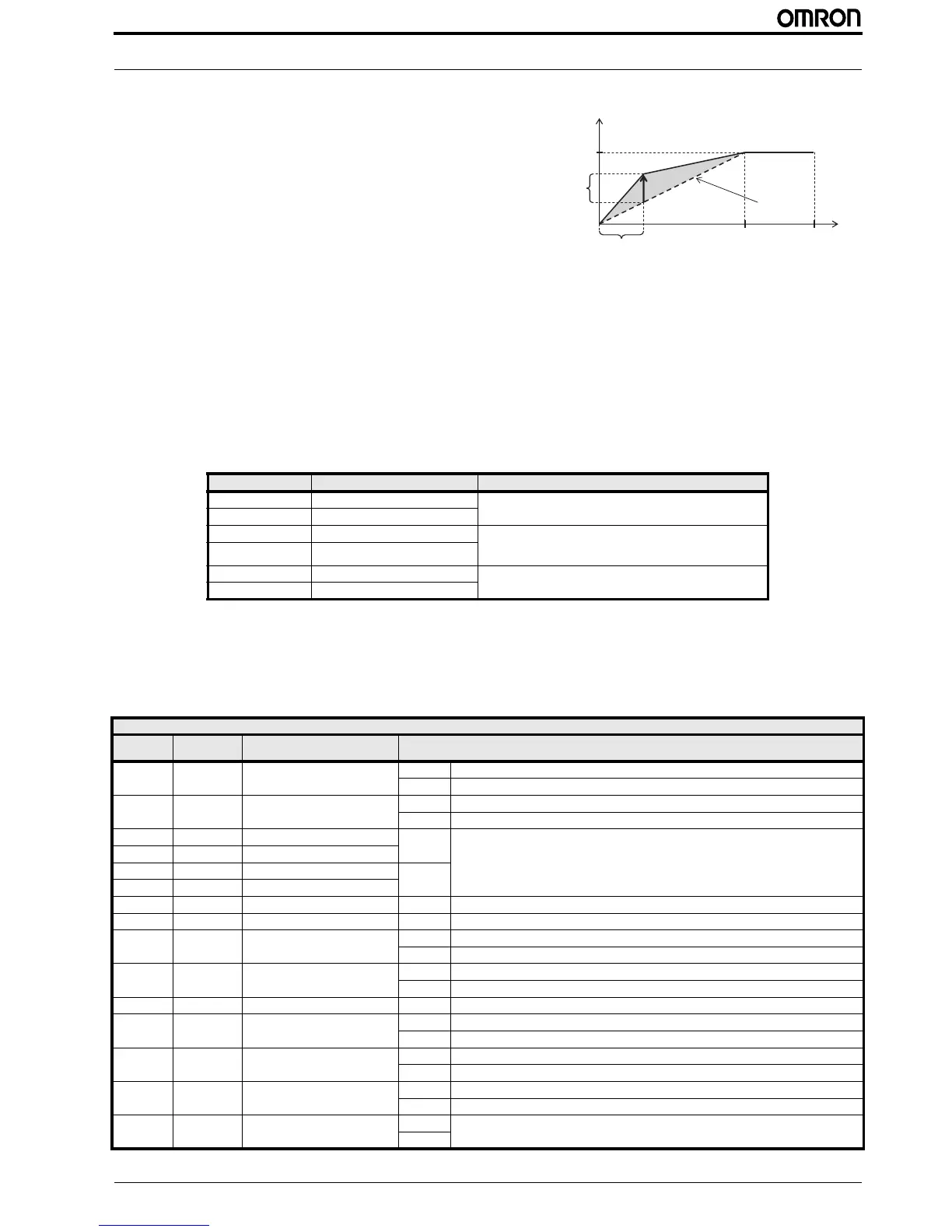
Manual torque boost (A042/A242, A043/A243)
• Adds the voltage set in A042/A242 and A043/A243 to the V/F
characteristics, and outputs the resulting voltage. The addition
value is set in percentage terms based on the AVR voltage
selection (A082) as 100%.
• The manual torque boost frequency (A043/A243) is set in per-
centage terms based on the base frequency as 100%.
• If you raise the set value of the manual torque boost (A042/
A242) be careful about motor overexcitation. Otherwise the
motor may burn out.
Simple torque boost (A041/A241)
• If simple torque boost is selected in the torque boost selection (A041/A241: 01), it operates to adjust the output voltage
depending on the load level.
• To select simple torque boost in the torque boost selection (A041/A241), set the motor capacity selection (H003/H203) and
motor pole number selection (H004/H204) according to your motor.
• You may avoid a possible overcurrent trip during deceleration by always setting the AVR selection to ON (A081: 00).
• Sufficient characteristics may not be obtained if you select two or more lower rank motor size than specified.
3.9 Digital inputs
The function codes in the following table let you assign between a wide range of functions to any of the five logic inputs for the
3G3JX inverter. The functions C001 through C005 configure the terminals [1] through [5] respectively. The “value” of these par-
ticular parameters is not a scalar value, but it is a discrete number that selects one option from many available options.
Parameter Parameter name Description
A041 Torque boost selection 00: Manual torque boost only
01: Automatic (simple) torque boost
A241 2nd torque boost selection
A042 Manual torque boost voltage Can boost starting torque between 0 and 20% above normal V/f
curve
0.0 to 20.0%
A242 2nd manual torque boost voltage
A043 Manual torque boost frequency Sets the frequency of the V/f breakpoint for torque boost
0.0 to 50.0%
A243 2nd manual torque boost frequency
Input function summary table
Option
code
Terminal
symbol
Function name Description
00 FW Forward command ON Inverter is in Run Mode, motor runs forward
OFF Inverter is in Stop Mode, motor stops
01 RV Reverse command ON Inverter is in Run Mode, motor runs reverse
OFF Inverter is in Stop Mode, motor stops
02 CF1 Multi-step speed setting binary 1 ON Binary encoded speed selection bit 3 to bit 0
03 CF2 Multi-step speed setting binary 2
04 CF3 Multi-step speed setting binary 3 OFF
05 CF4 Multi-step speed setting binary 4
06 JG Jogging ON Inverter is in Run Mode, output to motor runs at jog parameter frequency
07 DB External DC injection braking ON DC injection braking will be applied during deceleration
08 SET 2nd control selection ON The inverter uses 2nd motor parameters for generating frequency output to motor
OFF The inverter uses 1st (main) motor parameters for generating frequency output to motor
09 2CH 2-step acceleration/deceleration ON Frequency output uses 2nd-stage acceleration and deceleration values
OFF Frequency output uses standard acceleration and deceleration values
11 FRS Free-run stop ON Causes output to turn OFF, allowing motor to free run (coast) to stop
12 EXT External trip ON When assigned input transitions OFF to ON, inverter latches trip event and displays E 12
OFF No trip event for ON to OFF, any recorded trip events remain in history until reset
13 USP Power recovery restart protection ON The inverter will not resume a Run command
OFF The inverter will resume a Run command that was active before power loss
15 SFT Soft lock ON The keypad and remote programming devices are prevented from changing parameters
OFF The parameters may be edited and stored
16 AT Analog input switching ON Refer to Analog Input selection
OFF

 Loading...


