JX Quick Start Guide 27
PARAMETER LIST
4 PARAMETER LIST
The PDU (Process Data Unit) register number are addressed starting at zero. Therefore register numbered “0012h” addressed as
“0011h”. Register address value (transmitted on Modbus line) is 1 less than the Register number of the table
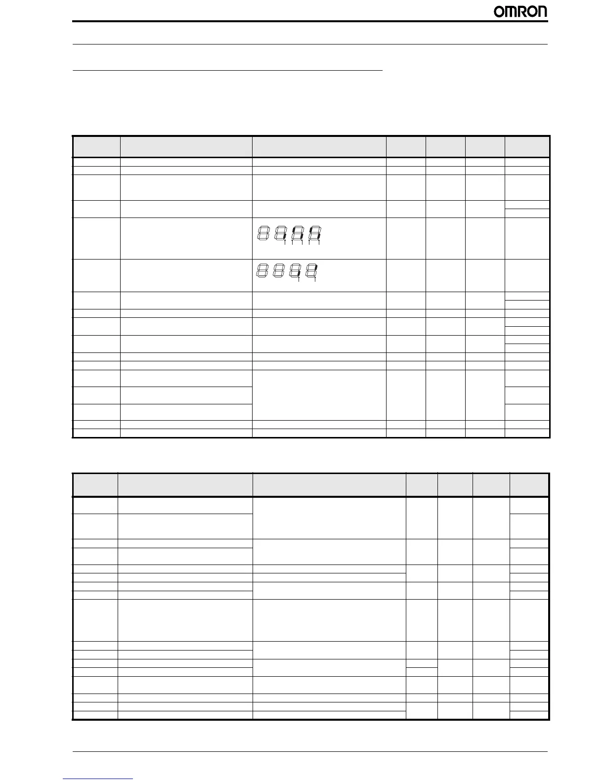
4.1 Parameter group D: Monitors
4.2 Parameter group A
Parameter No. Function name Monitoring or data range (digital operator)
Default
setting
Changes
during
operation
Unit
Modbus
address (hex)
d001 Output frequency monitor 0.0 to 400.0 - - Hz 1002
d002 Output current monitor 0.0 to 999.0 - - A 1003
d003 Rotation direction monitor F: Forward
o: Stop
r: Reverse
- - - 1004
d004 PID feedback value monitor 0.00 to 9999.
(Enabled when the PID function is enabled)
- - - 1005 (high)
1006 (low)
d005 Multi-function input monitor - - - 1007
d006 Multi-function output monitor - - - 1008
d007 Output frequency monitor (after conversion) 0.00 to 39960
(Output frequency x Conversion factor of b086)
- - - 1009 (high)
100A (low)
d013 Output voltage monitor 0. to 600. - - V 100C
d016 Total RUN time 0. to 99990 hours - - h 100E (high)
100F (low)
d017 Power ON time monitor 0. to 99990 hours - - h 1010 (high)
1011 (low)
d018 Fin temperature monitor 0.0 to 200.0 - - ºC 116A
d080 Fault frequency monitor 0. to 9999. - - - 0011
d081 Fault monitor 1 (Latest) Error code (condition of occurrence)
Output frequency [Hz]
Output current [A]
Internal DC voltage [V]
RUN time [h]
ON time [h]
- - - 0012 to 001B
d082 Fault monitor 2 001C to 0025
d083 Fault monitor 3 0026 to 002F
d102 DC voltage monitor 0.0 to 999.9 - - V 116C
d104 Electronic thermal monitor 0.0 to 100.0 - - % 116D
Parameter
No.
Function name Monitoring or data range (digital operator)
Default
setting
Changes
during
operation
Unit
Modbus
address
(hex)
A001 Frequency reference selection 00: Digital operator (FREQ adjuster)
01: Terminal
02: Digital operator (F001)
03: Modbus communication
10: Frequency operation result
00 No – 1019
A201 2nd frequency reference selection –
A002 RUN command selection 01: Terminal
02: Digital operator (F001)
03: Modbus communication
02 No – 101A
A202 2nd RUN command selection –
A003 Base frequency 30 to maximum frequency [A004] 50 No Hz 101B
A203 2nd base frequency 30 to 2nd maximum frequency [A204]
150C
A004 Maximum frequency 30. to 400. 50 No Hz 101C
A204 2nd maximum frequency
150D
A005 O/OI selection 00: Switches between O/OI via terminal AT
02: Switches between O/FREQ adjuster via terminal AT
03: Switches between FI/FREQ adjuster via terminal AT
04: O input only
05: OI input only
02 No – 101D
A011 O start frequency 0.0 to Max. frequency 0.0 No Hz 1020
A012 O end frequency 1022
A013 O start ratio 0. to 100. 0. No % 1023
A014 O end ratio 100. 1024
A015 O start selection 00: External start frequency (A011 set value)
01: 0 Hz
01 No – 1025
A016 O, OI sampling 1. to 17. 8. No – 1026
A020 Multi-step speed reference 0 0.0/starting frequency to max. frequency 6.0 Yes Hz 1029
A220 2nd multi-step speed reference 0 0.0/starting frequency to 2nd max. frequency
150F
Terminal
4, 2: ON
Terminal
5, 3, 1: OFF
ON
OFF
5 4 3 2 1

 Loading...


