3. Instructions
820
CS/CJ/NSJ Series Instructions Reference Manual (W474)
Flags
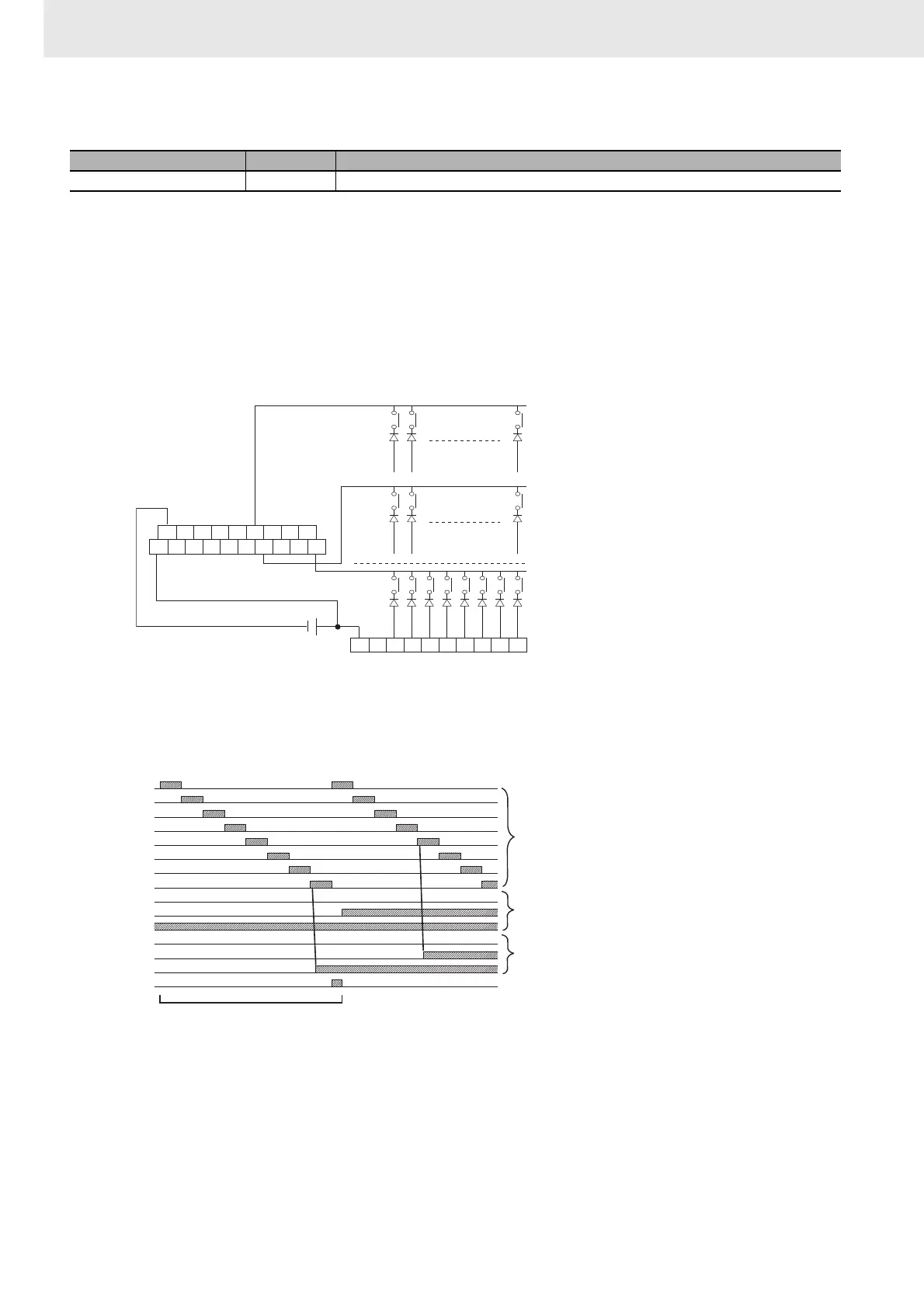
Function
MTR(213) outputs the selection signals to bits 00 to 07 of O, reads the data in order from bits 00 to 07
of I, and stores the 64 bits of data in the 4 words D through D+3. MTR(213) reads the status of the 64-
bit matrix every 24 CPU Unit cycles. The One Round Flag (bit 08 of O) is turned ON for one cycle in
every 24 cycles after each of the selection signals has been turned ON.
z External Connections
Connect the hexadecimal keypad to Input Unit contacts 0 to 7 and Output Unit contacts 0 to 7, as
shown in the following diagram.
The inputs and outputs can be connected to the following kinds of Basic I/O Units and High-density I/O
Units as long as they are not mounted in a SYSMAC BUS Remote I/O Rack.
• DC Input Units with 8 or more input points
• Transistor Output Units with 8 or more output points
z Timing Chart
Name Label Operation
Error Flag P_ER OFF
A8 A7 A6 A5 A4 A3 A2 A1 A0
A9 A8 A7 A6 A5 A4 A3 A2 A1 A0
B9 B8 B7 B6 B5 B4 B3 B2 B1 B0
OD212
ID211 I/O Unit
1
st
row
7
th
row
8
th
row
00
01
02
03
04
05
06
07
00
32
64
00
32
64
08
:
:
:
:
One round completed in 24 cycles
Selection signals
Matrix status
One Round Flag
Bits indicating status of inputs
(Bit ON when input is ON)

 Loading...


