141
Built-in Inputs Section 6-1
Restrictions on Quick-response Inputs
• Quick-response inputs 0 to 3 cannot be used when built-in inputs IN0 to
IN3 are being used as general-purpose inputs or high-speed counter
inputs.
• Quick-response input 3 cannot be used when high-speed counter input 0
is being used.
Quick-response input 2 cannot be used when high-speed counter input 1
is being used.
• Quick-response inputs 0 and 1 cannot be used when the origin search
function is enabled for pulse output 0 (enabled in the PLC Setup).
Quick-response inputs 2 and 3 cannot be used when the origin search
function is enabled for pulse output 1 (enabled in the PLC Setup).
Specifications
6-1-6 Hardware Specifications
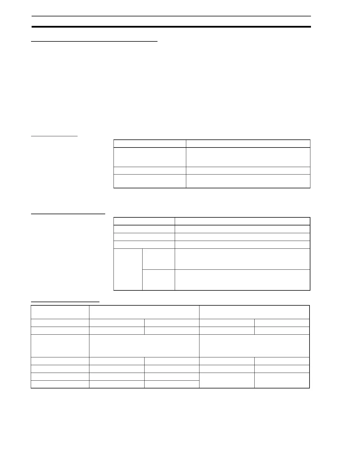
General Specifications
Input Characteristics
Item Specifications
Number of quick-response
inputs
4 inputs (The 4 input terminals are shared by the
quick-response inputs, high-speed counters, and
general-purpose inputs.)
Allocated data area CIO 2960 bits 00 to 03
Minimum detectable pulse
width
30 µs
Item Specifications
Number of inputs 10 inputs
Allocated data area CIO 2960 bits 00 to 09
Input methods 24-V DC inputs or line-driver inputs
Response
speed
ON
response
time
Default setting: 8 ms max.
(The input time constant can be set to 0 ms, 0.5 ms, 1 ms,
2 ms, 4 ms, 8 ms, 16 ms, or 32 ms in the PLC Setup.)
OFF
response
time
Default setting: 8 ms max.
(The input time constant can be set to 0 ms, 0.5 ms, 1 ms,
2 ms, 4 ms, 8 ms, 16 ms, or 32 ms in the PLC Setup.)
Input voltage specifi-
cations
24 V DC Line driver
Terminals IN0 to IN5 IN6 to IN9 IN0 to IN5 IN6 to IN9
Compatible sensors Two-wire method Two-wire method Line driver Line driver
Input voltage 24 V DC +10%, −15% RS-422 line driver
(conforming to AM26LS31 standards)
(Power supply voltage of 5 V ±5%)
Input impedance 3.6 kΩ 4.0 kΩ --- ---
Input current (typical) 6.0 mA 5.5 mA 13 mA 10 mA
ON voltage 17.4 V min. 17.4 V min. --- ---
OFF voltage 5.0 V/1 mA max. 5.0 V/1 mA max.
 Loading...


