22
I/O Specifications Section 3-1
Note In order for the counter inputs to satisfy the specifications shown in the table
above, it will be necessary to check the factors that can affect the pulses, such
as the type of output driver in the encoder, encoder cable length, and count
pulse frequency. In particular, the rise time and fall time may be too long and
the input waveform may not be within specifications when a long encoder
cable is used to connect an encoder that has 24-V open collector inputs.
When a long cable is connected, either shorten the encoder cable or use an
encoder with line driver outputs.
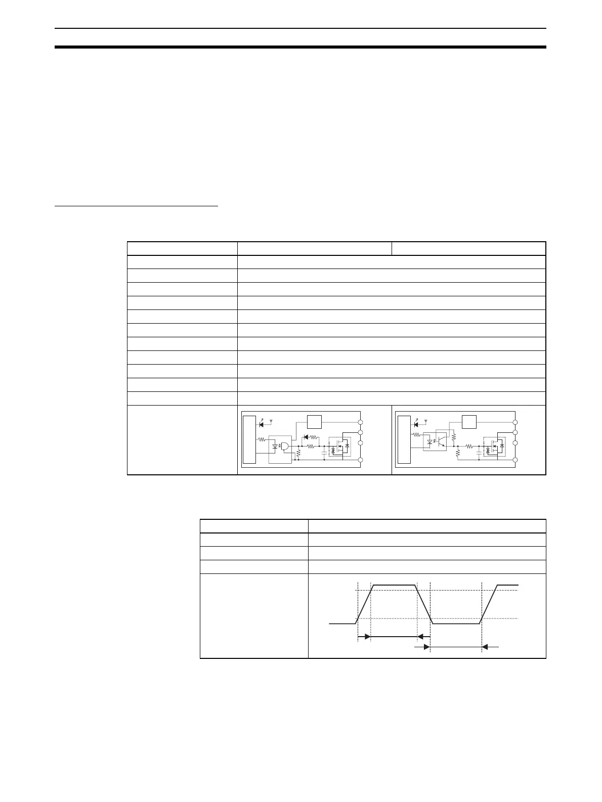
3-1-2 Output Specification
Transistor Outputs (Sinking)
General-purpose Output
Specifications
Pulse Output
Specifications (OUT0 to
OUT3)
Note 1. The values shown above are for a resistive load and do not consider the
impedance of the cable connecting the load.
2. The pulse waveform may be distorted by the connecting cable's imped-
ance, and thus the actual pulse width may be shorter than the values
shown above.
Output OUT0 to OUT3 OUT4 to OUT5
Rated voltage 5 to 24 V DC
Allowable voltage range 4.75 to 26.4 V DC
Max. switching capacity 0.3 A/output; 1.8 A/Unit
Number of circuits 6 outputs (6 outputs/common)
Max. inrush current 3.0 A/output, 10 ms max.
Leakage current 0.1 mA max.
Residual voltage 0.6 V max.
ON delay 0.1 ms max.
OFF delay 0.1 ms max.
Fuse None
External power supply 10.2 to 26.4 V DC 50 mA min.
Circuit configuration
+V
COM
OUT 0
to
OUT 3
Internal circuits
Fixed
voltage
circuit
+V
COM
OUT 4
to
OUT 5
Internal circuits
Fixed
voltage
circuit
Item Specifications
Max. switching capacity 30 mA, 4.75 to 26.4 V DC
Min. switching capacity 7 mA, 4.75 to 26.4 V DC
Max. output frequency 100 kHz
Output waveform
ON
OFF
90%
10%
2 µs min.
4 µs min.
 Loading...


