EasyManua.ls Logo

Omron CJ1M-CPU22 User Manual

Omron CJ1M-CPU22
267 pages
To Next Page IconTo Next Page
To Previous Page IconTo Previous Page
Page #244 background imageLoading...
Page #244 background image
215
Built-in Outputs Section 7-1
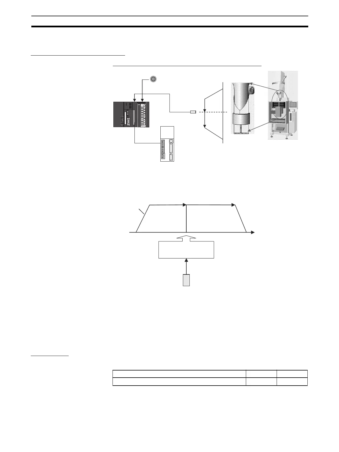
7-1-8 Feeding Wrapping Material: Interrupt Feeding
Specifications and Operation
Feeding Wrapping Material in a Vertical Pillow Wrapper
Operation Pattern Speed control is used to feed wrapping material to the initial position. When
the marker sensor input is received, fixed-distance positioning is performed
before stopping.
Operation
1,2,3... 1. Speed control is used to feed wrapping material to the initial position when
the Start Switch (CIO 00000) is activated.
2. When the Marker Sensor Input (IN0) is received, PLS2(887) is executed in
interrupt task 140.
3. Fixed-distance positioning is executed with PLS2(887) before stopping.
Preparation
PLC Setup Settings
Note The interrupt input setting is read when the power supply is turned ON.
Start Switch (CIO 000000)
Pulse output
(CW/CCW)
Marker sensor
(Built-in input IN0)
Position
control
Speed
control
10000 Hz
500 Hz/4 ms
(2710 hex)
(01F4 hex)
Speed
control
Position control
5,000 (1388 hex) pulses
output before stopping.
Input interrupt task
executes PLS2(887)
Marker sensor
input (IN0)
Setting details Address Data
Enable using built-in input IN0 as an interrupt input. 060 0011 hex

Table of Contents

Other manuals for Omron CJ1M-CPU22

Question and Answer IconNeed help?

Do you have a question about the Omron CJ1M-CPU22 and is the answer not in the manual?

Omron CJ1M-CPU22 Specifications

General IconGeneral
CPU ModelCJ1M-CPU22
Program Memory10K steps
Data Memory32K words
Power Supply24 VDC
Operating Temperature0 to 55 °C
Number of Timers/Counters256
Ethernet PortNo
Communication PortsRS-232C
Execution Speed (LD instruction)0.1 μs
High-speed Counter2 channels
Weight500g

Summary

PRECAUTIONS

Safety Precautions

Critical safety measures to prevent injury or damage when using PLC and PLC Units.

SECTION 3 I/O Specifications and Wiring

3-1 I/O Specifications

Provides detailed specifications for all built-in inputs and outputs.

3-2 Wiring

Explains connector pin assignments and wiring methods for system connections.

SECTION 4 Data Area Allocation and PLC Setup Settings

4-2 PLC Setup Settings

Explains the configuration settings required in CX-Programmer for built-in I/O.

SECTION 5 High-speed Counter/Pulse Output Instructions

5-5 SPEED OUTPUT: SPED(885)

Details the SPED(885) instruction for setting output frequency and starting pulse output.

5-7 PULSE OUTPUT: PLS2(887)

Details the PLS2(887) instruction for outputting pulses with acceleration/deceleration.

5-8 ACCELERATION CONTROL: ACC(888)

Explains ACC(888) for controlling pulse output with specified acceleration/deceleration rates.

5-9 ORIGIN SEARCH: ORG(889)

Describes the ORG(889) instruction for performing origin search or origin return operations.

SECTION 6 Built-in I/O Function Descriptions

6-3 Origin Search and Origin Return Functions

Explains the detailed application of origin search and origin return functions.

Related product manuals