126
Creating Routing Tables Section 6-4
6-4-3 Routing Table Setting Examples
■ Example 1: Local Network Table for a PLC With Multiple Units Mounted
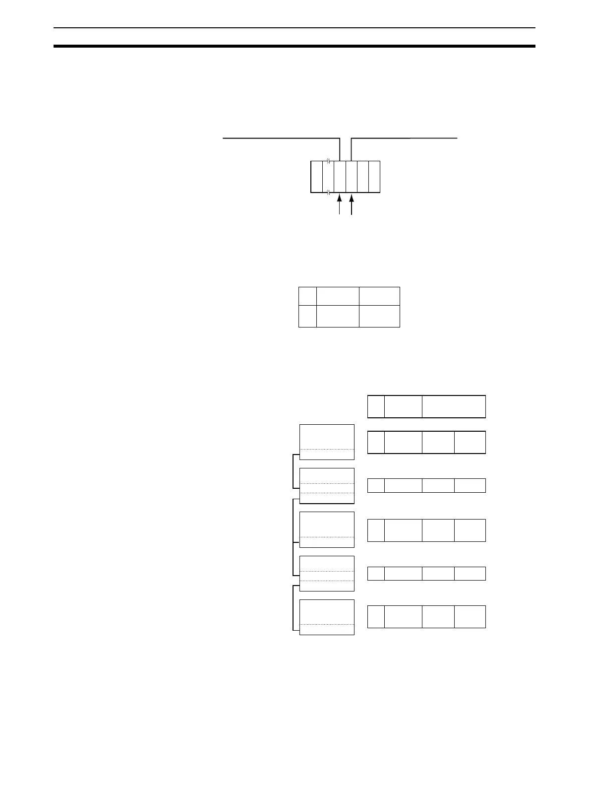
This example shows the local network table settings for a PLC to which multi-
ple CPU Bus Units are mounted.
■ Example 2: Three Interconnected Networks
This example shows the relay network table settings for three different inter-
connected networks.
In the table for PLC #3, for example, if network #A is taken as the end net-
work, then network #B becomes the relay network and node #c becomes the
relay node. If network #C is taken as the end network, then network #B still
becomes the relay network and node #e becomes the relay node.
A
B
a
b
No.
1
2
P
S
C
P
U
C
L
K
E
T
N
Ethernet network
(Network #A)
Controller Link network
(Network #B)
Unit #a Unit #b
PS: Power Supply Unit
CPU: CPU Unit
ETN: Ethernet Unit
CLK: Controller Link Unit
Local Network Table
Local
network
CPU Bus
Unit
1
2
B
C
A
A
b
b
1C B e
1
2
A
C
B
B
c
e
1
2
A
B
C
C
f
f
1A B c
Relay Network Table
No.
End
network
Relay
network
Node
PLC #1
Node #a
Network #A
PLC #2
Node #b
Node #c
Node #d
PLC #3
Network #B
Network #C
Node #e
PLC #4
Node #f
Node #g
PLC #5

 Loading...


