25
Nomenclature and Functions Section 1-6
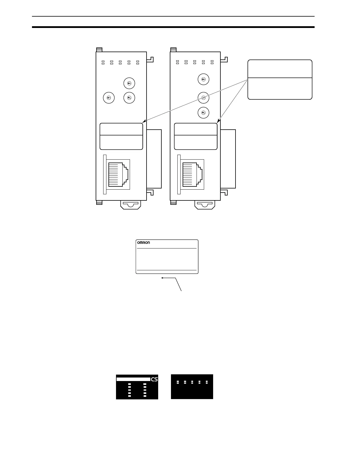
Each communications device connected to the Ethernet network is allocated
a unique Ethernet address. For the Ethernet Unit, this Ethernet address is
shown on the right side of the Unit as a 12-digit hexadecimal number.
Note The Ethernet address can also be checked using the FINS command, CON-
TROLLER DATA READ. For details, refer to 7-3-2 CONTROLLER DATA
READ on page 162.
1-6-2 Indicators
The status of the indicators show the operating status of the Ethernet Unit, as
shown below.
Example
Attach the label to the front
of the Ethernet Unit between
the node number switches
and the Ethernet connector.
x16
0
0
1
2
3
4
5
6
7
8
9
A
B
C
D
E
F
0
1
2
3
4
5
6
7
8
9
A
B
C
D
E
F
UNIT
No.
ETN21
100BASE-TX
10BASE-T
0
1
2
3
4
5
6
7
8
9
A
B
C
D
E
F
NODE
No.
x16
1
IP ADDRESS
SUBNET MASK
133.113. 0. 42
255.255.255.0
IP ADDRESS
SUBNET MASK
133.113. 0. 42
255.255.255.0
IP ADDRESS
SUBNET MASK
133.113. 0. 42
255.255.255.0
RUN ERC SD RD
ERH TCP FTP HOST100M
LINK
UNIT
No.
ETN21
100BASE-TX
10BASE-T
NODE
No.
x16
0
x16
1
0
1
2
3
4
5
6
7
8
9
A
B
C
D
E
F
0
1
2
3
4
5
6
7
8
9
A
B
C
D
E
F
0
1
2
3
4
5
6
7
8
9
A
B
C
D
E
F
RUN ERC SD RD
ERH TCP FTP HOST100M
LINK
• Unit Version 1.5 or Later • Unit Version 1.4 or Earlier
ETHERNET UNIT
CJ1W-ETN21
OMRON Corporation MADE IN JAPAN
Lot No.
@@@@@@@@@@@@
Ethernet Address
Ethernet address (12 digits)
ETN21
RUN
ERC
SD
RD
LNK
100M
ERH
TCP
FTP
HOST
RUN
ETN21
ERC SD RD
ERH TCP FTP HOST
LNK
100M
CS1W-ETN21
(100Base-TX)
CJ1W-ETN21
(100Base-TX)

 Loading...


