23
Nomenclature and Functions Section 1-6
1-6 Nomenclature and Functions
This section describes Ethernet Unit component names, settings, and LED
indicators.
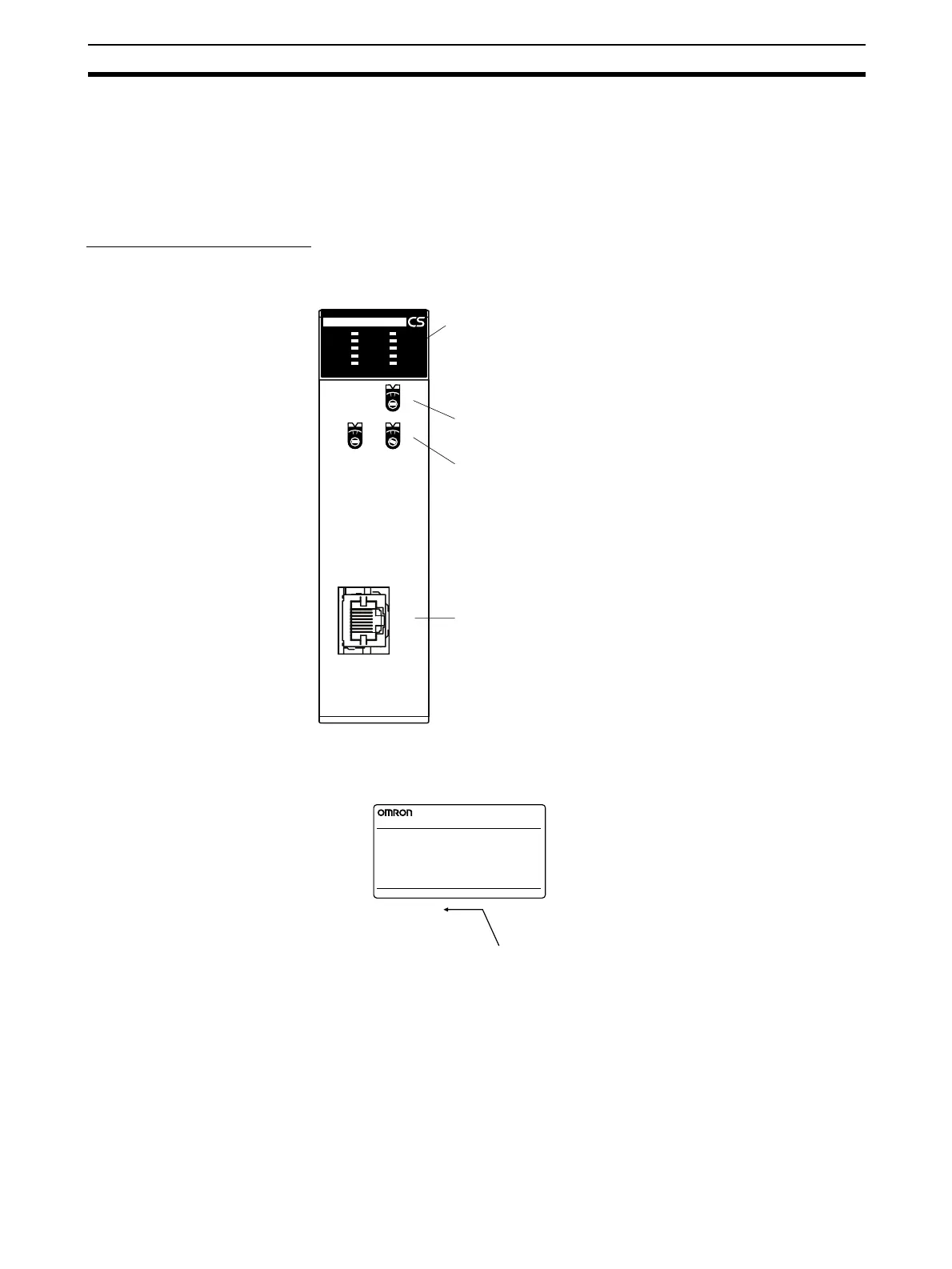
1-6-1 Component Names
CS-series Ethernet Units
CS1W-ETN21 (100Base-TX)
Each communications device connected to the Ethernet network is allocated
a unique Ethernet address. For the Ethernet Unit, this Ethernet address is
shown on the right side of the Unit as a 12-digit hexadecimal number.
Note The Ethernet address can also be checked using the FINS command, CON-
TROLLER DATA READ. For details, refer to 7-3-2 CONTROLLER DATA
READ on page 162.
Front
Indicators
Unit Number Switch
Display the operating status of the Unit.
Node Address Switches
Ethernet Connector
Used to connect the Ethernet twisted-pair cable.
NODE
NO.
×16
0
×16
1
UNIT
NO.
0
1
0
Used to set the Ethernet Unit's unit
number in one digit hexadecimal.
Used to set the Ethernet Unit's FINS
node number in two digits hexadecimal.
ETN21
RUN
ERC
SD
RD
LNK
100M
ERH
TCP
FTP
HOST
100BASE-TX
10BASE-T
ETHERNET UNIT
CS1W-ETN21
OMRON Corporation MADE IN JAPAN
Lot No.
@@@@@@@@@@@@
Ethernet Address
Ethernet address (12 digits)

 Loading...


