39
Creating I/O Tables Section 2-6
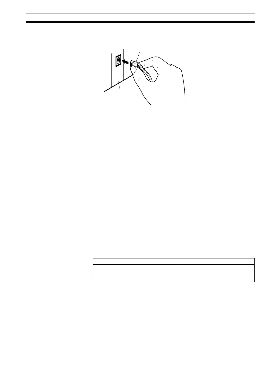
3. Connect the cable to the connector on the Ethernet Unit. Be sure to press
in the cable until it locks into place.
2-6 Creating I/O Tables
2-6-1 I/O Table Overview
I/O tables are used to identify Units mounted to the PLC, and to allocate I/O to
them. With CS-series and CJ-series PLCs, whenever there is a change to the
Unit configuration it is necessary to create I/O tables and register the Units to
the CPU Unit.
The I/O tables can be created in the following ways.
• Using the CX-Programmer offline.
• Using the CX-Programmer online, with the Units mounted to the PLC.
• Using the Programming Console, with the Units mounted to the PLC.
• Using the CPU Unit's automatic I/O allocation at startup. (This method is
available for the CJ Series only.)
From here on, operations involving the Programming Console are
described.
2-6-2 Connecting Programming Devices to the PLC
To create the I/O tables, connect a Programming Device (such as a CX-Pro-
grammer or Programming Console) to the PLC.
Applicable Programming
Devices
The following Programming Devices can be used with CS/CJ-series PLCs.
Programming Console
CX-Programmer (Version 3.20 or Higher) and CX-Integrator
The operations are explained here using a Programming Console. For details
regarding the CX-Programmer and the CX-Integrator, refer to the CX-Pro-
grammer User’s Manual. Refer to the CX-Integrator Operation Manual (W445)
for connection procedures and operating procedures for the CX-Integrator.
CX-Integrator is software that comes with CX-One and is automatically
installed when CX-One is installed.
Ethernet Unit
RJ45 Modular Connector
Example: CS1W-ETN21
Model number Key Sheet (required) Recommended cable (required)
C200H-PRO27-E CS1W-KS001-E CS1W-CN224 (cable length: 2.0 m)
CS1W-CN624 (cable length: 6.0 m)
CQM1-PRO01-E CS1W-CN114 (cable length: 0.1 m)

 Loading...


