Com Data
for Modbus
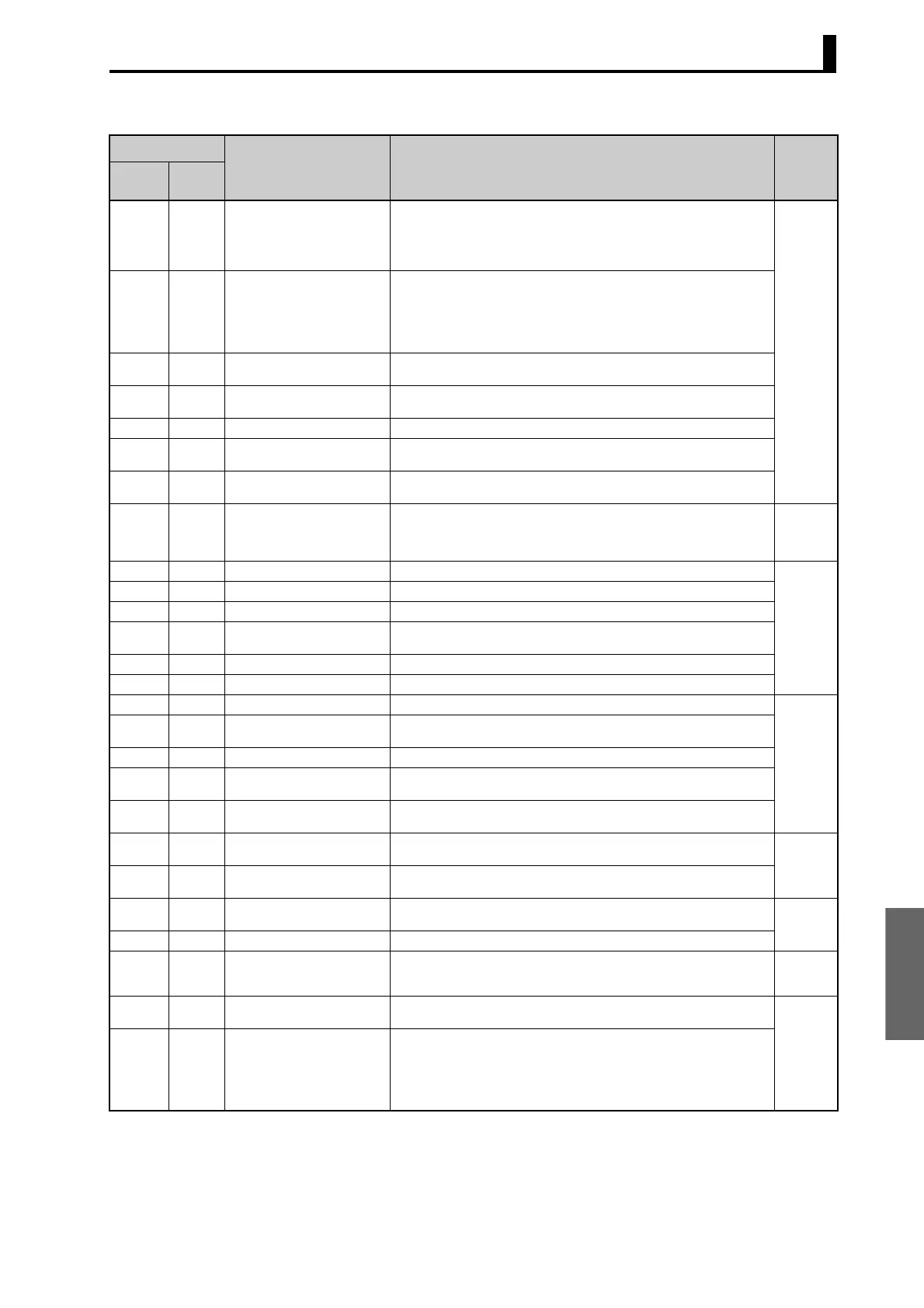
6.1 Variable Area (Setting Range) List
6-3
Note 1: The parameter for the currently selected bank will be accessed.
Note 2: The parameter for the currently selected PID set will be accessed. For setup area 1, however, the currently selected PID
set is fixed at PID1.
Address
Parameter name Setting (monitor) value Level
Four-byte
mode
Two-byte
mode
0500 2500 Operation/Adjustment Protect H'00000000 (0): No restrictions in operation and adjustment levels
H'00000001 (1): Move to adjustment level is prohibited.
H'00000002 (2): Display and change of only “PV” and “PV/SP” parameters is
allowed.
H'00000003 (3): Display of only “PV” and “PV/SP” parameters is allowed.
Protect
0502 2501 Initial Setting/Communications
Protect
H'00000000 (0): Move to initial setting/communications setting level is allowed.
(Move to advanced function setting level is displayed.)
H'00000001 (1): Move to initial setting/communications setting level is allowed.
(Move to advanced function setting level is not displayed.)
H'00000002 (2): Move to initial setting/communications setting level is prohib-
ited.
0504 2502 Setting Change Protect H'00000000 (0): OFF (Changing of setup on controller display is allowed.)
H'00000001 (1): ON (Changing of setup on controller display is prohibited.)
0506 2503 PF Key Protect H'00000000 (0): OFF
H'00000001 (1): ON
0508 2504 Move to Protect Level H'FFFFF831 to H'0000270F (
−1999 to 9999)
050A 2505 Password to Move to Protect
Level
H'FFFFF831 to H'0000270F (
−1999 to 9999)
(Can only be set. The monitor value is always H’00000000.)
050C 2506 Parameter Mask Enable H'00000000 (0): OFF
H'00000001 (1): ON
0600 2600 Manual MV Standard: H'FFFFFFCE to H'0000041A (
−5.0 to 105.0)
Heating/cooling: H'FFFFFBE6 to H'0000041A (
−105.0 to 105.0)
Position proportional (Closed and direct setting of position proportional MV
ON): H'FFFFFFCE to H'0000041A (
−5.0 to 105.0)
Manual
Control
0602 2601 Set Point (See note 1.) SP lower limit to SP upper limit Operation
0604 2602 Remote SP Monitor Remote SP lower limit to Remote SP upper limit
0608 2604 Heater Current 1 Value Monitor H'00000000 to H'00000226 (0.0 to 55.0)
060A 2605 MV Monitor (Heating) Standard: H'FFFFFFCE to H'0000041A (
−5.0 to 105.0)
Heating and cooling: H'00000000 to H'0000041A (0.0 to 105.0)
060C 2606 MV Monitor (Cooling) H'00000000 to H'0000041A (0.0 to 105.0)
060E 2607 Valve Opening Monitor H'FFFFFF9C to H'0000044C (
−10.0 to 110.0)
0700 2700 Cooling Coefficient (See note 2.) H'00000001 to H'0000270F (0.01 to 99.99) Adjustment
0708 2704 Dead Band Temperature: H'FFFFB1E1 to H'00007E90 (
−1999.9 to 3240.0)
Analog: H'FFFFF831 to H'0000270F (
−199.9 to 999.9)
070A 2705 Manual Reset Value H'00000000 to H'000003E8 (0.0 to 100.0)
070C 2706 Hysteresis (Heating) Temperature: H'00000001 to H'00007E90 (0.1 to 3240.0)
Analog: H'00000001 to H'0000270F (0.1 to 999.9)
070E 2707 Hysteresis (Cooling) Temperature: H'00000001 to H'00007E90 (0.1 to 3240.0)
Analog: H'00000001 to H'0000270F (0.1 to 999.9)
0710 2708 Control Period (Heating) H'00000000 (0): 0.5
H'00000001 to H'00000063 (1 to 99)
Initial
setting
0712 2709 Control Period (Cooling) H'00000000 (0): 0.5
H'00000001 to H'00000063 (1 to 99)
0714 270A Position Proportional Dead
Band
H'00000001 to H'00000064 (0.1 to 10.0) Adjustment
0716 270B Open/Close Hysteresis H'00000001 to H'000000C8 (0.1 to 20.0)
0718 270C SP Ramp Time Unit H'00000000 (0): EU/second
H'00000001 (1): EU/minute
H'00000002 (2): EU/hour
Advanced
function
setting
071A 270D SP Ramp Set Value
(See note 1.)
H'00000000 (0): OFF
H'00000001 to H'00007E90 (1 to 32400)
Adjustment
071E 270F MV at Stop Standard: H'FFFFFFCE to H'0000041A (
−5.0 to 105.0)
Heating/cooling: H'FFFFFBE6 to H'0000041A (
−105.0 to 105.0)
Position proportional (Floating or direct setting of position proportional MV
OFF): H'FFFFFFFF to H'00000001 (
−1 to 1)
Position proportional (Closed and direct setting of position proportional MV
ON): H'FFFFFFCE to H'0000041A (
−5.0 to 105.0)
 Loading...


