Modbus
5.4 Detailed Description of the Services
5-11
Process Value in Two-byte Mode
• Address: H’2000; Read data: H’03E8 (100.0 °C)
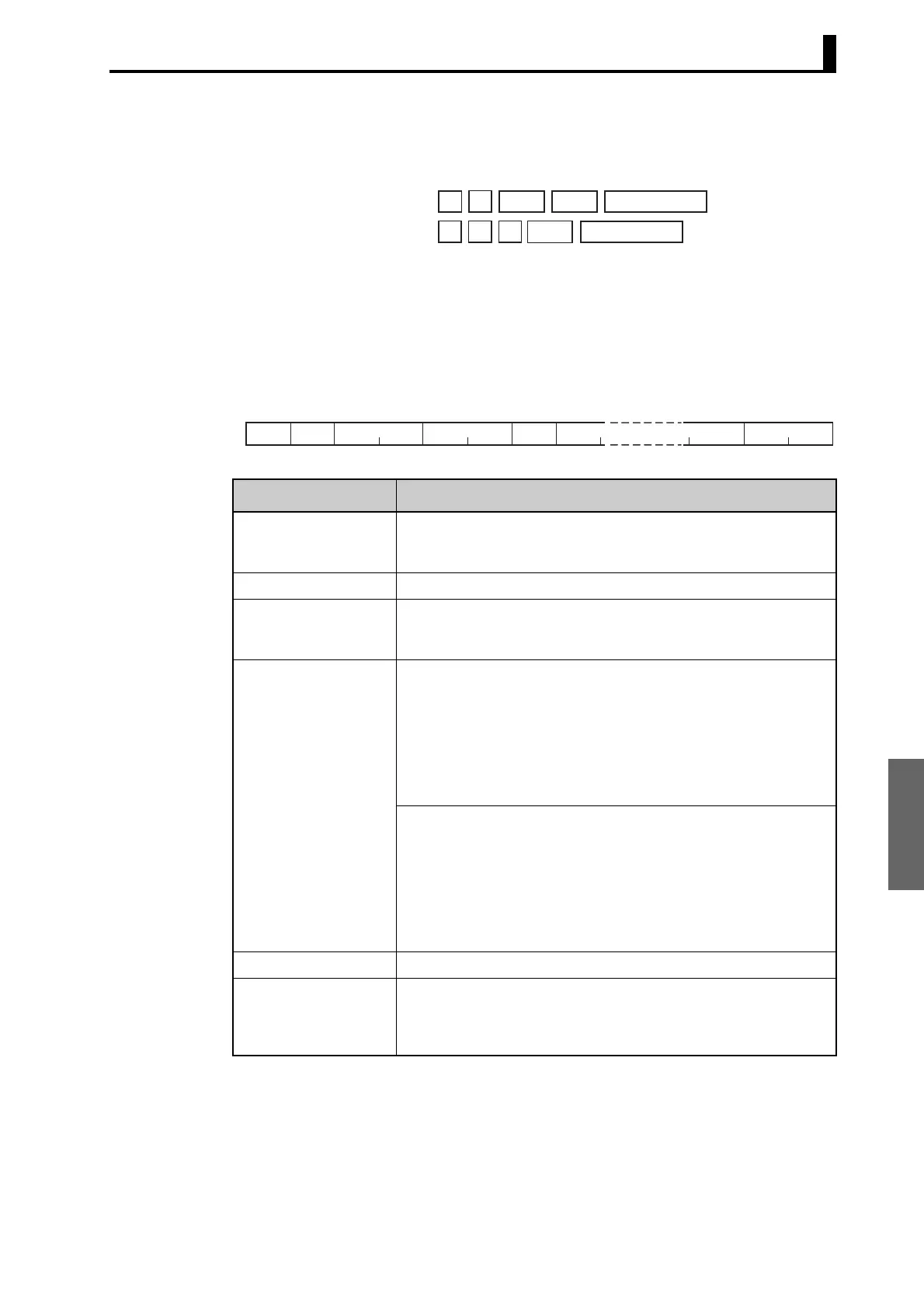
■ Variable Write, Multiple
To write data to the variable area, set the required data in the command
frame, as shown in the following diagram.
Command Frame
Command:
Response:
01
01 03
03
02
00 00 00 01
03 E8
8F CA (CRC-16)
B8 FA (CRC-16)
Name Description
Slave address Specify the E5CN/AN/EN-H’s unit number.
The unit number can be set between H’01 and H’63 hexadecimal (1
to 99 decimal).
Function code The Write Variable Area function’s function code is H’10.
Write start address Specify the starting address where the setting data will be written.
See SECTION 6 Communications Data for Modbus for details on
addresses.
Number of elements Four-byte Mode
Specify 2 times the number of setting data items as the number of
elements to be written.
The setting range for the number of elements is H’0002 to H’0068 (2
to 104).
When H'0068 is set, 52 items of setting data can be read.
Example: When writing 2 items of setting data, set the number of ele-
ments to H’0004.
Two-byte Mode
Specify the number of setting data items to be written as the number
of elements.
The setting range for the number of elements is H'0001 to H'0068 (1
to 104).
When H'0068 is set, 104 items of setting data can be read.
Example: When reading two items of setting data, set the number of
elements to H'0002.
Byte count Specify the number of bytes of write data.
CRC-16 This check code is calculated with the data from the slave address to
the end of the data.
For details on the CRC-16 calculation, see CRC-16 Calculation
Example in 5.1 Data Format on page 5-3.
Number of
Elements
Slave
address
Function
code
Write
start address
Byte
count
11 2 21
H'10
2
CRC-16
0 to 208 (2 × 10⁴)
Write data (for the
number of elements)
 Loading...


