114
Using the Transfer Output Section 4-14
Transfer Scaling • Reverse scaling is possible by setting the Transfer Output Lower Limit
parameter larger than the Transfer Output Upper Limit parameter. If the
Transfer Output Lower Limit and Transfer Output Upper Limit parameters
are set to the same value when 4 to 20 mA is set, the transfer output will
be output continuously at 0% (4 mA).
• If the SP, SP during SP ramp, or PV is selected, the Transfer Output
Lower Limit and Transfer Output Upper Limit parameters will be forcibly
initialized to the respective upper and lower setting limits for changes in
the upper and lower limits of the SP limiter and the temperature unit.
If the MV for heating or MV for cooling is selected, the Transfer Output
Lower Limit and Transfer Output Upper Limit parameters will be initialized
to 100.0 and 0.0, respectively, when a switch is made between standard
control and heating/cooling control using the Standard or Heating/Cooling
parameter.
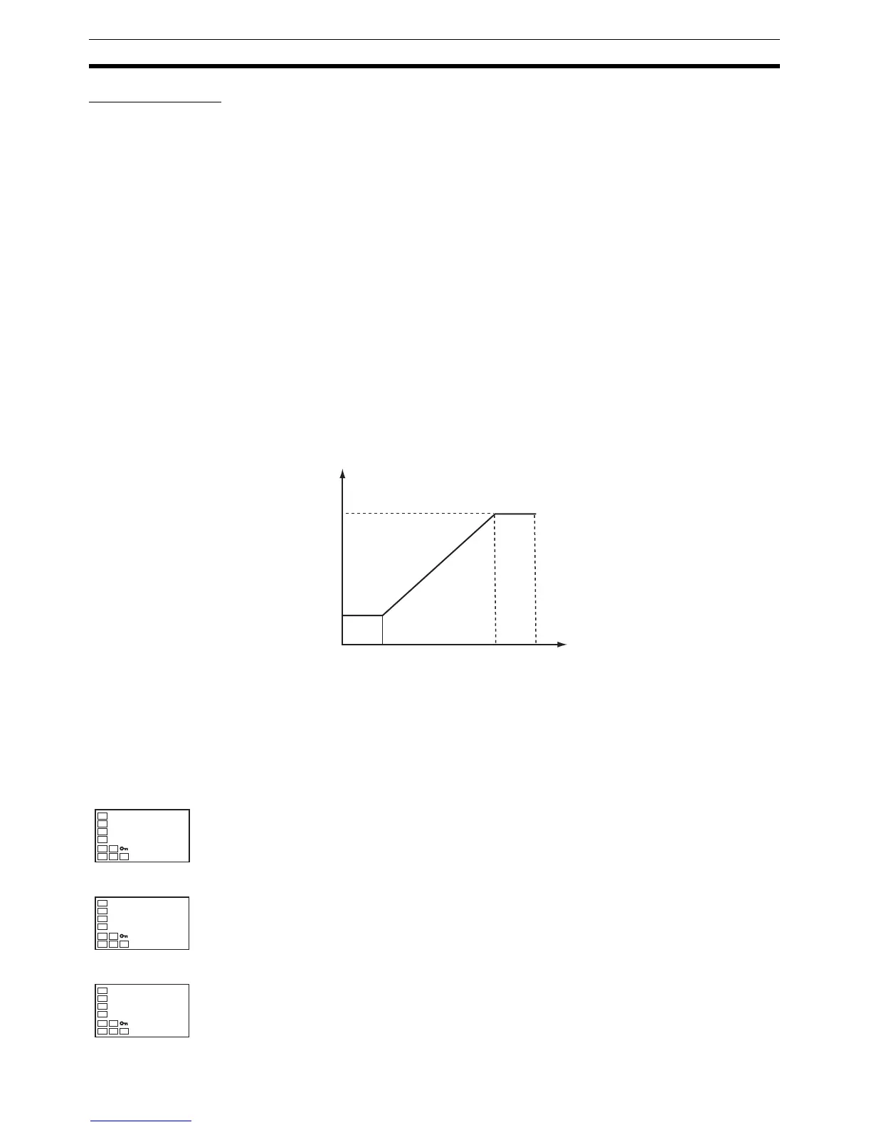
• The output current when the linear current type is set to 4 to 20 mA, the
transfer output upper limit is set to 90.0, and the transfer output lower limit
is set to 10.0 is shown in the following graph.
• For scaling from 0.0% to 100.0%, the output for
−5.0 to 0.0 will be the
same value as for 0.0%, and the output for 100.0 to 105.0 will be the
same value as for 100.0%
Operating Procedure The following procedure sets the transfer output for an SP range of
−50 to
200.
100
90
100
20
4
Output current (mA)
MV (%)
Transfer output
lower limit
Transfer output
upper limit
(The above graph is for when the linear current output type is set to 4 to 20 mA.)
Operation Level
Initial Setting Level
1. Press the O Key for at least three seconds to move from the operation
level to the initial setting level.
Initial Setting Level
2. Select the Transfer Output Type parameter by pressing the M Key.
C
25
100
PV/SP
in-t
0
Input Type
tr-t
off
Transfer Output
Type

 Loading...


