241
Thermocouple Calibration (Thermocouple/Resistance Thermometer Input)
Section 6-3
6-3-1 Preparations
• Set the cold junction compensator designed for compensation of internal
thermocouples to 0
°C. Make sure that internal thermocouples are dis-
abled (i.e., that tips are open).
• In the above figure, STV indicates a standard DC current/voltage source.
• Use the compensating conductor designed for the selected thermocou-
ple. When thermocouples R, S, E, B, W, or PLII or an infrared temperature
sensor is used, the cold junction compensator and the compensating con-
ductor can be substituted with the cold junction compensator and the
compensating conductor for thermocouple K.
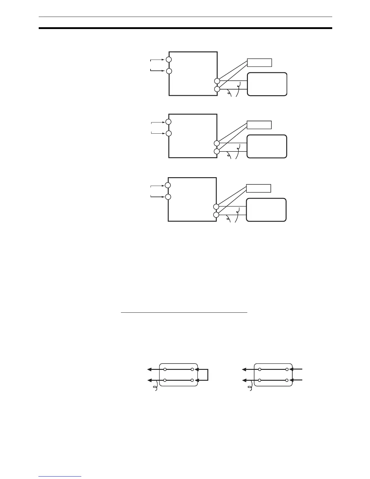
■ Connecting the Cold Junction Compensator
Correct process values cannot be obtained if you touch the contact ends of
the compensating conductor during calibration of a thermocouple. Accord-
ingly, short-circuit (enable) or open (disable) the tip of the thermocouple inside
the cold junction compensator as shown in the figure below to create a con-
tact or non-contact state for the cold junction compensator.
E5CN
STV
0°C/32°F
4
5
9
10
−
+
E5CN-U
STV
0°C/32°F
2
1
11
10
−
+
Input power supply
Input power supply
Compensating conductor
Compensating conductor
Cold junction
compensator
Cold junction
compensator
E5AN/EN
STV
0°C/32°F
19
20
2
1
−
+
Input power supply
Compensating conductor
Cold junction
compensator
E5CN
E5CN-U
E5AN
E5EN
E5CN
E5CN-U
E5AN
E5EN
0°C/32°F
0°C/32°F
Compensatin

 Loading...


