132
Logic Operations Section 4-22
Operating Procedure This procedure sets the PV Status Display Function parameter to ALM1.
4-22 Logic Operations
4-22-1 The Logic Operation Function (CX-Thermo)
• The logic operation function logically calculates as 1 or 0 the Controller
status (alarms, SP ramp, RUN/STOP, auto/manual, etc.) and the external
event input status, and outputs the results to work bits. The work bit status
can be output to auxiliary or control outputs, and operating status can be
switched according to the work bit status.
• Work bit logic operation can be set from 1 to 8. Set them to No operation
(Always OFF) (the default) when the work bits are not to be used. When
logic operations are being used, a dot will be displayed on the No. 2 dis-
play of the adjustment level display
Initial Setting Level
1. Press the O Key for at least three seconds to move from the operation
level to the initial setting level.
Initial Setting Level
2. Select the Move to Advanced Function Setting Level parameter by press-
ing the M Key.
Advanced Function Setting Level
3. Use the D Key to enter the password (−169). It is possible to move to the
advanced function setting level by either pressing the M Key or waiting
two seconds without pressing any key.
4. Press the M Key to select the PV Status Display Function parameter.
5. Press the U Key to select ALM1.
Initial Setting Level
6. Press the O Key for at least one second to move to the initial setting lev-
el.
Operation Level
7. Press the O Key for at least one second to move to the operation level.
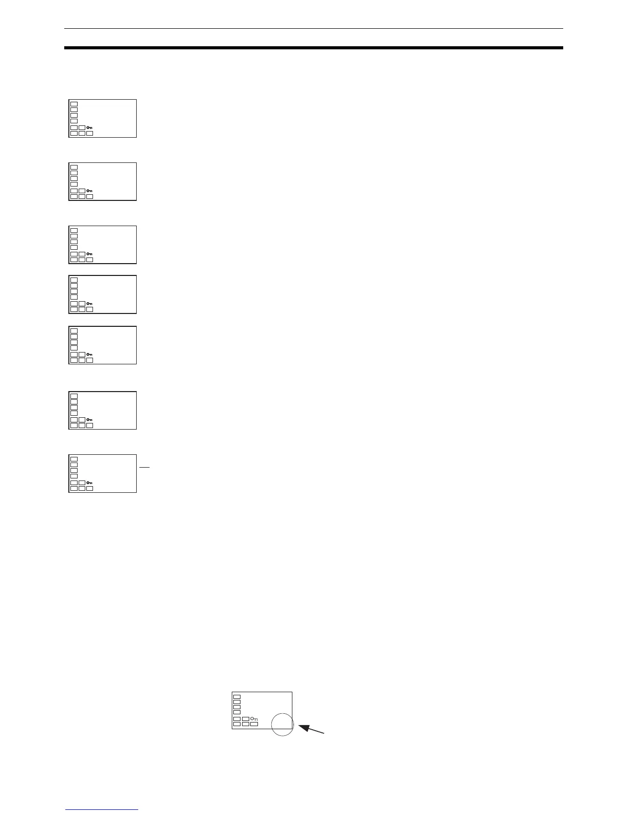
If the Alarm 1 status is ON, PV and ALM1 will be alternately displayed.
in-t
5
Input Type
amov
-169
Move to Ad-
vanced Function
Setting Level
init
off
Parameter
Initialization
pvst
off
PV Status
Display
Function
pvst
alm1
PV Status
Display
Function
in-t
5
Input Type
C
25
100
alm

 Loading...


