53
Determining PID Constants (AT, ST, Manual Setup) Section 3-8
Note PID Constants
When control characteristics are already known, PID constants can be set
directly to adjust control. PID constants are set in the Proportional Band (P),
Integral Time (I), and Derivative Time (D) parameters in the adjustment level.
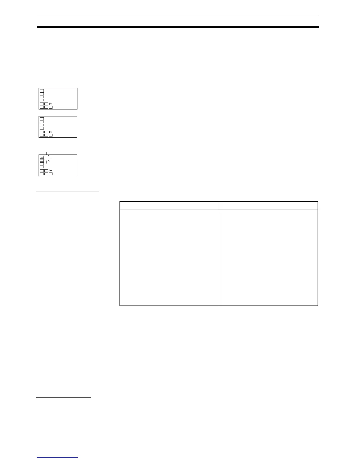
Operating Procedure This procedure executes self-tuning (ST).
Startup Conditions Self-tuning by step response tuning (SRT) is started when the following condi-
tions are met after program execution is started and the set point is changed.
Note (1) The previous SRT-implemented set point is the set point that was used for
calculating the PID constants for the previous SRT.
(2) In this state, the measurement point is within the ST stable range.
(3) In this state, the change width of the PV every 60 seconds is within the
ST stable range or less.
In the following instances, PID constants are not changed by self-tuning (ST)
for the present set point.
1,2,3... 1. When the PID constants have been changed manually with ST set to ON.
2. When auto-tuning (AT) has been executed.
ST Stable Range
Operating Procedure The ST stable range determines the condition under which ST (self-tuning)
functions.
Initial Setting Level
1. Press the O Key for at least three seconds to move from the operation
level to the initial setting level.
2. Select the ST parameter by pressing the M Key.
3. Press the U Key to select on. ON is the default.
Operation Level
4. To return to the operation level, press the O Key for at least one second.
The temperature display flashes during self-tuning (ST) execution.
in-t
5
Input Type
st
on
ST
C
25
100
PV
At start of operation When set point is changed
1. The set point at the start of operation
differs from the set point when the pre-
vious SRT was executed. (See note 1.)
2. The difference between the tempera-
ture at the start of operation and the set
point is greater both of the following:
(Present proportional band × 1.27 +
4°C) and the ST stable range.
3. The temperature at the start of opera-
tion is lower than the set point during
reverse operation, and is larger than
the set point during direct operation.
4. There is no reset from input errors.
1. The new set point differs from the set
point used when the previous SRT was
executed. (See note 1.)
2. The set point change width is greater
both of the following: (Present propor-
tional band × 1.27 + 4°C) and the ST
stable range.
3. During reverse operation, the new set
point is larger than the set point before
the change; and during direct opera-
tion, the new set point is smaller than
the set point before the change.
4. The temperature is stable. (See note
2.) (Equilibrium with the output amount
at 0% when the power is turned ON is
also all right.) (See note 3.)

 Loading...


