139
Logic Operations Section 4-22
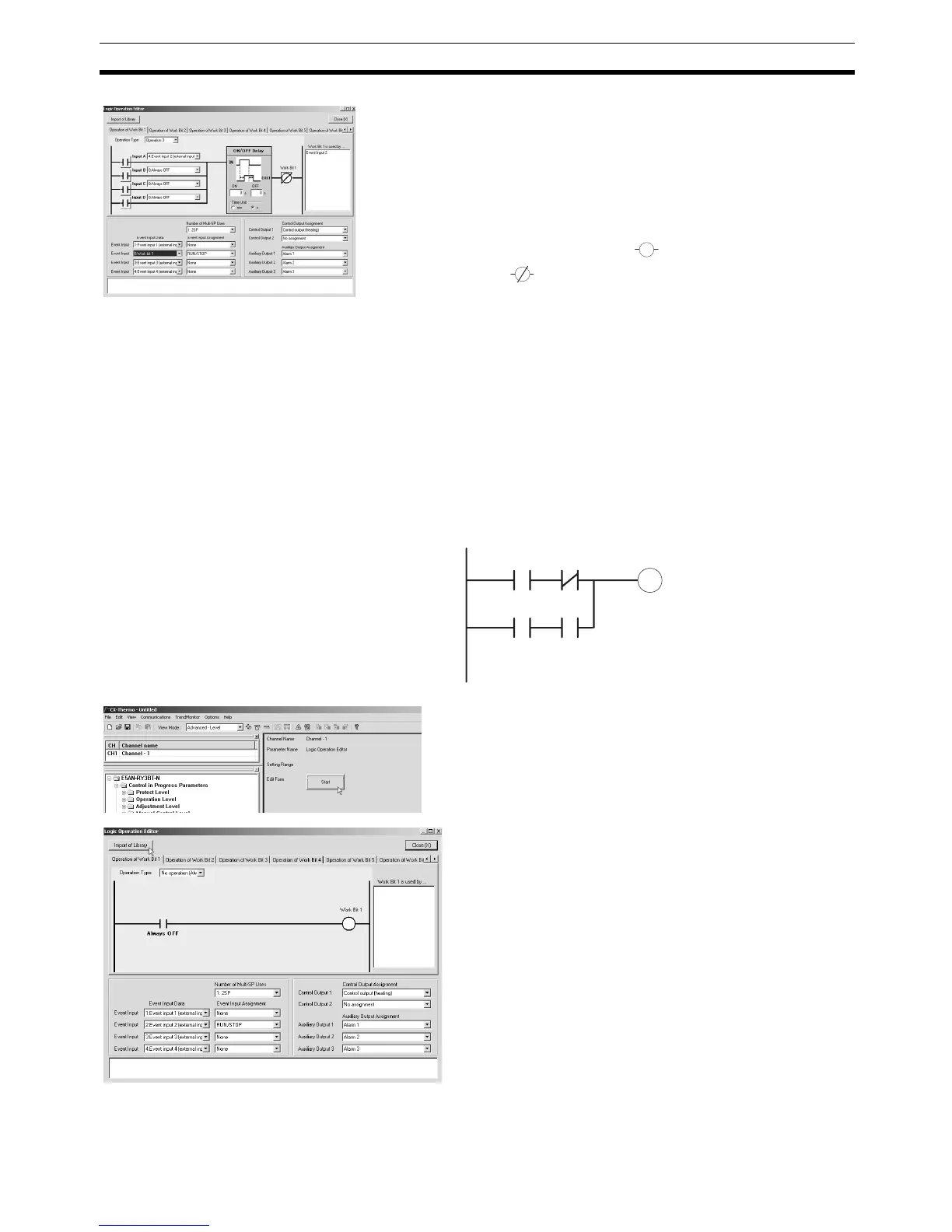
Operating Procedure This procedure outputs alarm 1 status to auxiliary output 1 during operation
(RUN). A library object is used to make the setting.
3. Set the operation by selecting one of the following:
Work bit 1 input assignment A = 4: Event input 2 (ex-
ternal input)
Work bit 1 input assignment B = 0: Always OFF
Work bit 1 input assignment C = 0: Always OFF
Work bit 1 input assignment D = 0: Always OFF
4. Invert work bit 1. Click (Normally open) to change
it to (Normally closed).
5. Assign RUN/STOP to event input 2. Set “5: Work bit 1”
for the event input data for event input 2, and set “RUN/
STOP” for the assignment function.
6. Closing the Logic Operation Editor Dialog Box
Click the Close Button.
This completes the procedure for setting parameters
using the CX-Thermo. Transfer the settings to the Control-
ler to set the Controller. Refer to CX-Thermo help for the
procedure to transfer the settings.
Alarm 1
RUN/STOP
Work bit 1
Always OFF Always OFF
1. Select Logic Operation Editor from the CX-Thermo
tree, and click the Start Button.
2. Click the Import of Library Button.