A-11
Memory Display Image on PLC I/O
The memory display image on PLC I/O varies depending on the PLC to be used.
Using data output to the Data Output area of the PLC link from the serial data output processing item
as an example, this section illustrates how the memory display image varies depending on the model.
●Data storage image (Data Output area DM1000)
When the PLC link Data Output area is set to DM1000, data is stored as follows in the PLC I/O memo-
ry.
Up to 8 expressions can be registered in the serial output flow on the Sensor Controller side. If 8 ex-
pressions are registered, data is stored as follows.
DM1000
+0
Expression 0 Expression 1 Expression 2 Expression 3 Expression 4
DM1010
Expression 5 Expression 6 Expression 7
+1 +2 +3 +4 +5 +6 +7 +8 +9
●CX-Programmer PLC I/O memory display image
As an example, if 3 data items, expression 0 (DATA0) = 1.000, expression 1 (DATA1) = 200.000, and
expression 2 (DATA2) = 1000.000, are output from the Sensor Controller, they are stored to the PLC
Link area as measurement data as follows.
DM1000 1000
DM1010
200000 1000000
Decimal number with sign (2ch-separated display)
00
+8+6+4+2+0
00000
Fixed point (Number of significant figures is 3)
“1.000”
Data is stored to the PLC I/O memory as follows for a decimal number per channel.
DM1000 0 16960 151000
+3+2+1+0
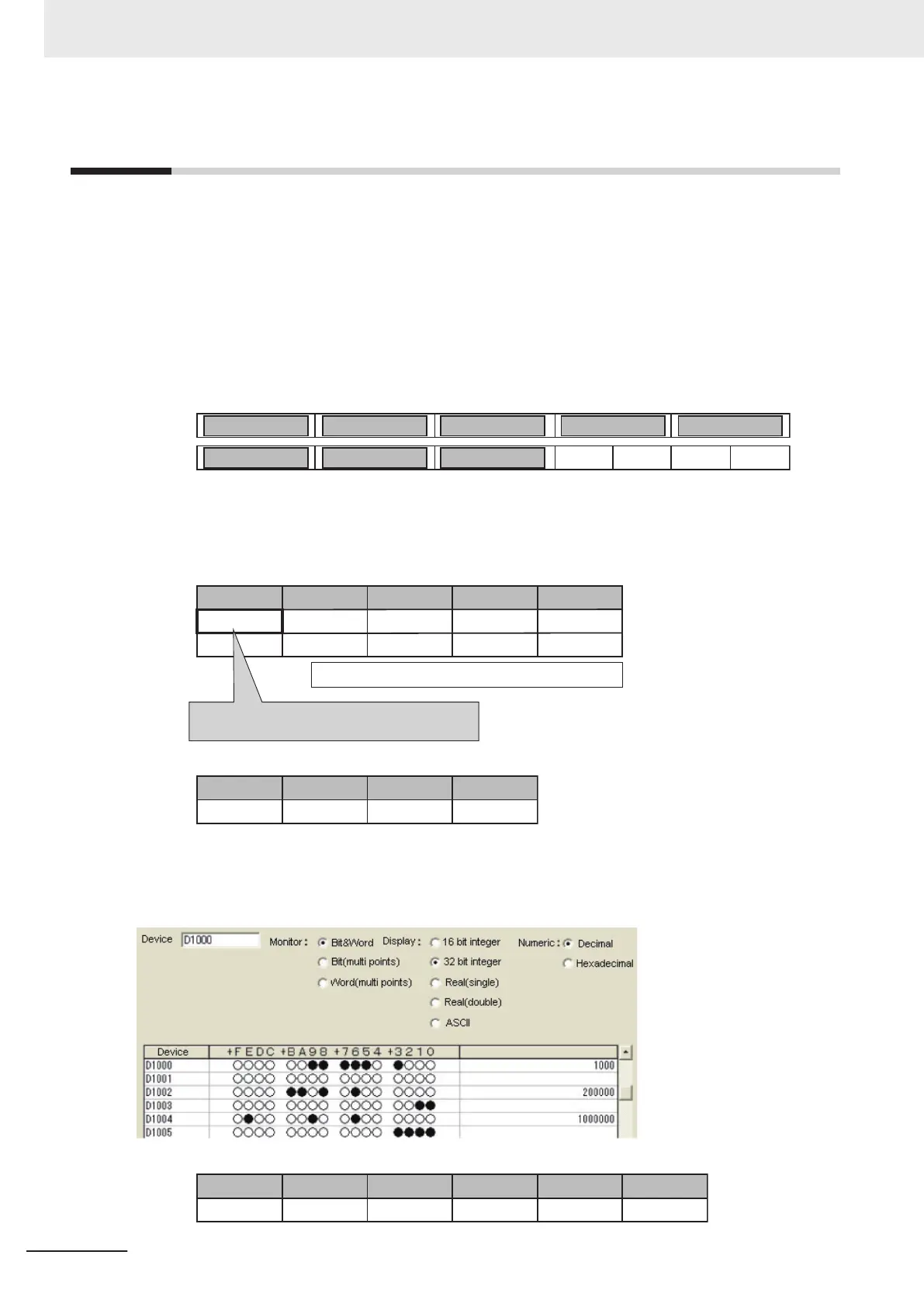
●GX-Developer PLC I/O memory display image
As an example, if 3 data items, expression 0 (DATA0) = 1.000, expression 1 (DATA1) = 200.000, and
expression 2 (DATA2) = 1000.000, are output from the Sensor Controller, they are stored to the PLC
Link area as measurement data as follows.
Data is stored to the PLC I/O memory as follows for a decimal number per channel.
DM1000 0 3392 31000
+3+2+1+0
16960 15
+5+4
Appendices
A - 36
FH/FHV Series Vision System User’s Manual (Z365-E1)
 Loading...


