82
5-3-4 Reference Input Signal
The following are the reference signals for all input ranges.
Input type Input range Reference
input signal L
Reference
input signal H
Input
terminals
DC voltage
a Ud
0.00 V 199.99 V 1 and 4
input
b Ud
0.000 V 19.999 V 2 and 4
c Ud
0.0000 V 1.9999 V 3 and 4
d Ud
0.00 mV 199.99 mV 3 and 4
e Ud
1.0000 V 5.0000 V 2 and 4
DC current
a ad
0.00 mA 199.99 mA 1 and 4
input
b ad
0.000 mA 19.999 mA 2 and 4
c ad
0.0000 mA 1.9999 mA 3 and 4
d ad
4.000 mA 20.000 mA 2 and 4
AC voltage
a Ua
0.0 V 400.0 V 1 and 4
input
b Ua
0.00 V 199.99 V 1 and 4
c Ua
0.000 V 19.999 V 2 and 4
d Ua
0.0000 V 1.9999 A 3 and 4
AC current
a aa
0.000 A 10.000 A 1 and 4
input
b aa
0.0000 A 1.9999 A 1 and 4
c aa
0.00 mA 199.99 mA 2 and 4
d aa
0.000 mA 19.999 mA 3 and 4
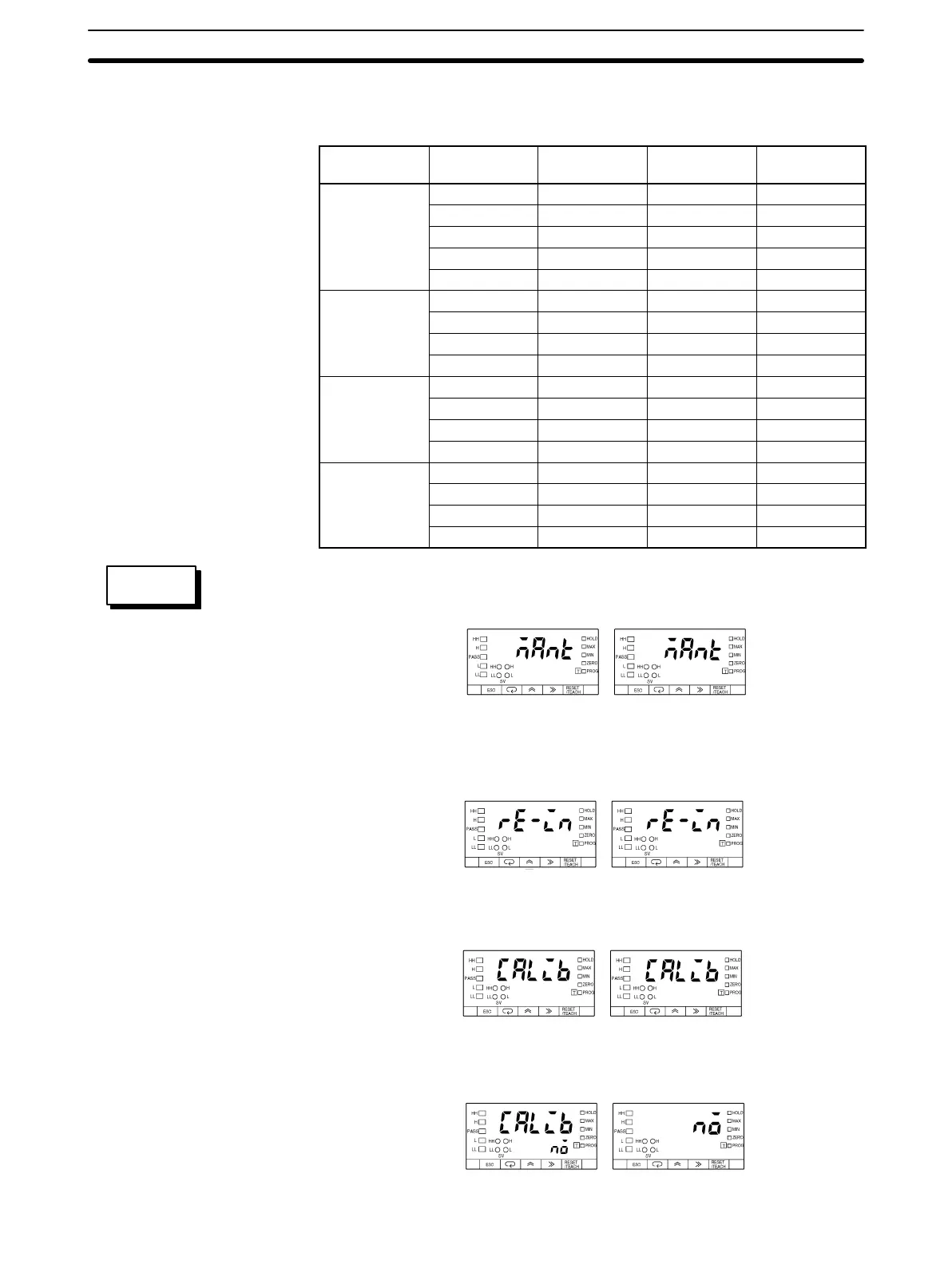
Follow the steps described below to calibrate the input range eĆUd.
Set Value LED Display Model Basic Model
1, 2, 3... 1. Press the Mode Key for more than one second while the mant maintenance
mode setting is displayed. The reĆin initialization setting will be displayed.
Set Value LED Display Model Basic Model
2. Press the Mode Key to display the calib field calibration setting.
Set Value LED Display Model Basic Model
3. Press the Shift Key so that the K3NX will be ready for the field calibration.
Set Value LED Display Model Basic Model
SETTING
EXAMPLE
Maintenance Mode
Section 5-3
AUDIN - 7 bis rue de Tinqueux - 51100 Reims - France - Tel : 03.26.04.20.21 - Fax : 03.26.04.28.20 - Web : http: www.audin.fr - Email : info@audin.fr
 Loading...