9. Appendix 1 Detailed Settings of the Tag Data Links
46
9.2. Relationship between the Destination Device and the Global Variables
Global variables must be sorted in order of offsets of the destination device when setting the
tag data link parameters.
The relationship between the memory allocation (offset) of the destination device and the
global variables are shown below.
■Output area (Controller → Displacement Sensor)
Variable Data type Data size
EIPOutput S_EIPOutput 24 bytes
Offset (word) Destination device data Name Data type
EIPOutput.CommonControlFlag.F
*4
BOOL[32]
+0 and +1
Control output 1
*1
(32 bits)
(Data type: U_EIPFlag)
EIPOutput.CommonControlFlag.W
*4
DWORD
EIPOutput.SensorHead1ControlFlag.F
*5
BOOL[32]
+2 and +3
Control output 2
*2
(32 bits)
(Data type: U_EIPFlag)
EIPOutput.SensorHead1ControlFlag.W
*5
DWORD
EIPOutput.SensorHead2ControlReserve.F
*6
BOOL[32]
+4 and +5
Control output 3
*3
(32 bits)
(Data type: U_EIPFlag)
EIPOutput.SensorHead2ControlReserve.W
*6
DWORD
+6 and +7
Command code
(CMD-CODE)
EIPOutput.CommandCode DWORD
+8 EIPOutput.CommandParam1 UINT
+9 EIPOutput.CommandParam2 UINT
+10 and +11
Command parameter
(CMD-PARAM)
EIPOutput.CommandParam3 DINT
*1: Sensor head common control signal
*2: Sensor head 1 control signal
*3: Sensor head 2 control signal (reserved)
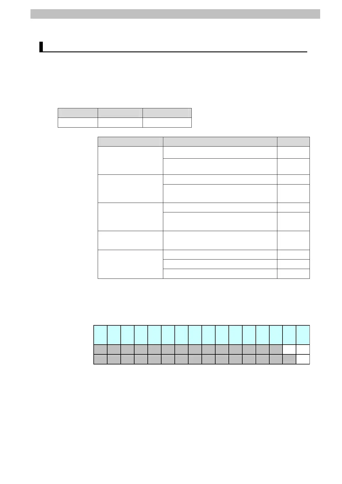
*4: Details on the allocation of sensor head common control signal
Allocation of EIPOutput.CommonControlFlag.F variable
Offset
(word)
15 14 13 12 11 10 9 8 7 6 5 4 3 2 1 0
+0
SYNC
EXE
+1
ERCLR
EXE: Control command execution bit: Turns ON when the Controller
instructs execution of control commands to the displacement
sensor.
SYNC: Measurement synchronous start bit: Turns ON when the user
Controller instructs measurement synchronization to the
displacement sensor.
ERCLR: Error clear bit: Turns ON when the displacement sensor ERR
signal turns OFF.

 Loading...


