6-46
6-7 Object Dictionary
OMNUC G5-series AC Servomotors and Servo Drives User’s Manual (with Built-in EtherCAT Communications)
6
Drive Profile
The value obtained by adding the value of this object (60B2 hex) and the torque feed-forward
value calculated from the Control effort (60FA hex) and related objects (3112 hex and 3113 hex)
is used as a torque feed-forward input value for the torque command which is calculated by
comparing the Control effort (60FA hex) and the speed feedback. The Block Diagram for Position
Control Mode on page 6-7 shows the relationship of above description. Refer to 11-11 Feed-
forward Function on page 11-29 for details.
This object sets and controls the latch function.
There are two channels, Latch 1 (bits 1 to 7) and Latch 2 (bits 8 to 15).
Bits 0 and 8 execute latching when changed from 0 to 1.
To change the settings, set bit 0 or 8 to 0 and then to 1 again.
Latching is disabled in the following cases.
When communications is in the Init state.
When the Statusword (6041 hex) bit 9 (remote) is 0 (local).
For details on the latch function, refer to Touch Probe Function (Latch Function) on page 6-9.
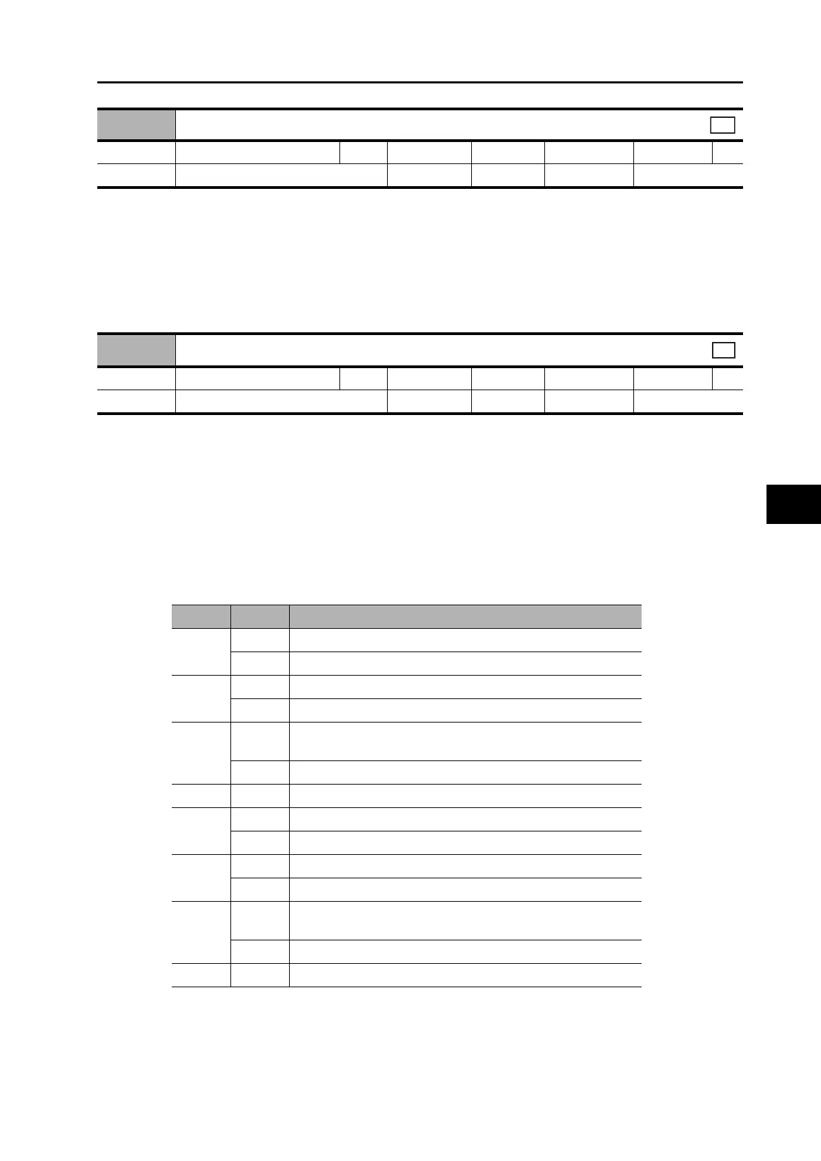
Bit Descriptions
60B2 hex
Torque offset
Range −5000 to 5000 Unit 0.1% Default 0 Attribute A
Size 2 bytes (INT16) Access RW PDO map Possible
csp
60B8 hex
Touch probe function (Latch function)
Range − Unit − Default 0 Attribute A
Size 2 bytes (U16) Access RW PDO map Possible
All
Bit Code Description
0
0 Latch 1 is disabled.
1 Latch 1 is enabled.
1
0 Trigger first event (Latch on the first trigger).
1 Continuous (Latch continuously on trigger input).
2
0
Latch on the signal selected in the Touch Probe Trigger
Selection (3758 hex).
1 Latch on the encoder's phase-Z signal.
3 to 7 0 Reserved (always set to 0).
8
0 Latch 2 is disabled.
1 Latch 2 is enabled.
9
0 Trigger first event (Latch on the first trigger).
1 Continuous (Latch continuously on trigger input).
10
0
Latch on the signal selected in the Touch Probe Trigger
Selection (3758 hex).
1 Latch on the encoder's phase-Z signal.
11 to 15 0 Reserved (always set to 0).

 Loading...


