3 - 11
3 Specifications
G5-series Linear Motors/Servo Drives With Built-in EtherCAT Communications
3-1 Servo Drive Specifications
3
3-1-8 Control Output Circuits
z External Latch Input Signals (EXT1, EXT2, and EXT3)
• These are the external input signals to latch the actual value in the feedback pulse counter.
• The encoder position data is obtained when the External Latch Input is turned ON.
• With the default settings, External Latch Input 1 is allocated to pin 12, External Latch Input 2 to pin
11, and External Latch Input 3 to pin 10.
Precautions for Correct UsePrecautions for Correct Use
• The external latch inputs are detected by on the rising edge of the signal, but the minimal
signal ON and OFF widths must be 2 ms.
• The external latch inputs can only be set to N.O. (normally open) contacts.
• The external latch inputs can be allocated to pins 10 to 12 only.
z Monitor Inputs (MON0, MON1, and MON2)
• These are the general-purpose monitor inputs.
• The general-purpose monitor inputs do not affect operation and can only be monitored from the
host controller.
• With the default settings, MON0 is allocated to pin 13.
z Positive Force Limit Input (PCL)/Negative Force Limit Input (NCL)
• Turn ON these inputs to limit the force to the value set in the Positive Force Limit (3525 hex) or the
Negative Force Limit (3526 hex).
• While the input is ON, operation continues within the force limit.
• With the default settings, the inputs are not allocated.
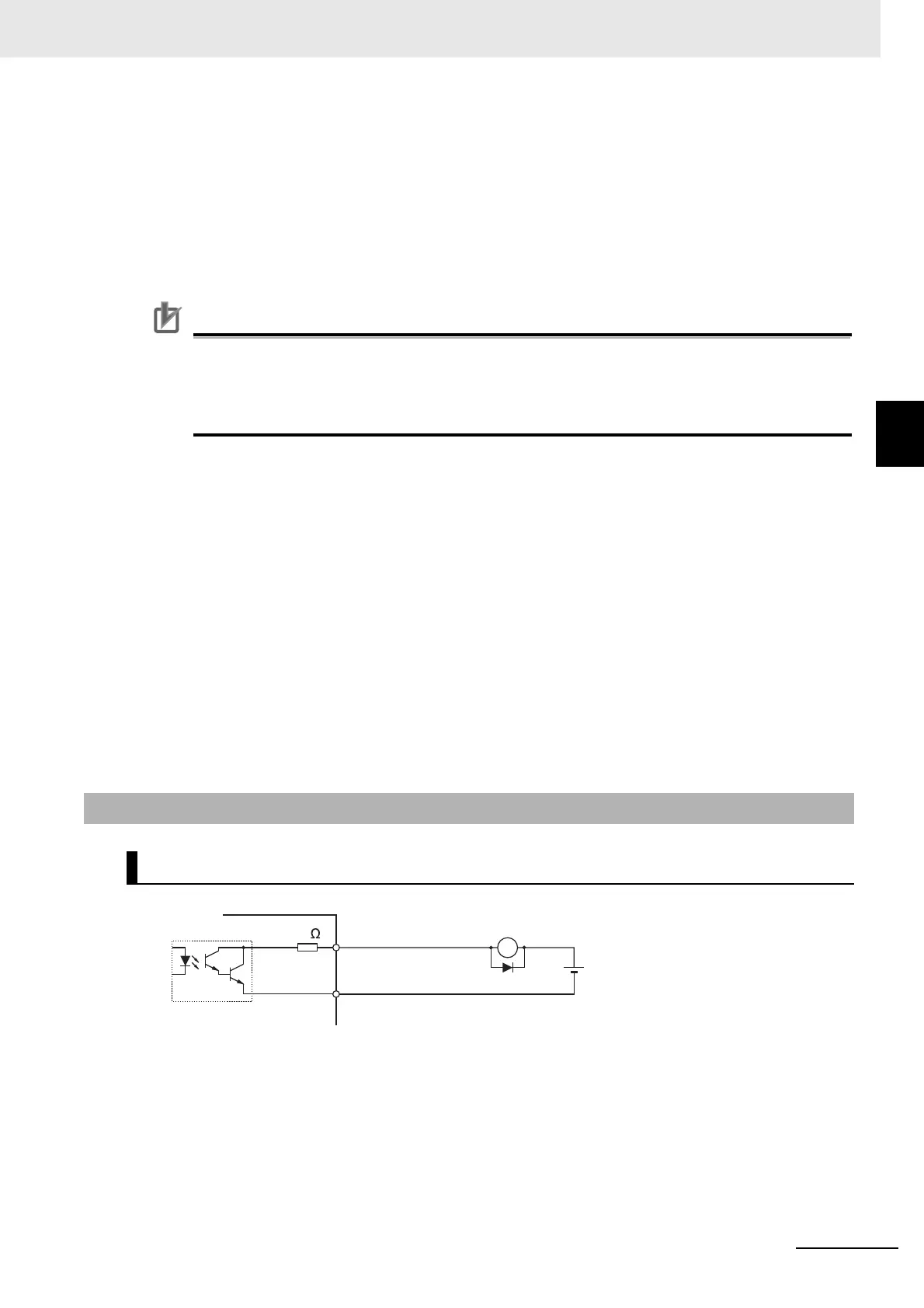
*1 When driving a relay directly with an output signal, always insert a diode as shown in the above figure.
Use high-speed diodes.
3-1-8 Control Output Circuits
Sequence Outputs
OUTMCOM, ALMCOM
X
Di
10
OUTM1, OUTM2, ALM
Di: Surge voltage prevention diode
*1
External power supply
12 to 24 VDC
Maximum service voltage:
30 VDC or less
Maximum output current:
50 mA or less
Servo Drive

 Loading...