Chapter 3
3-14
System Design and Installation
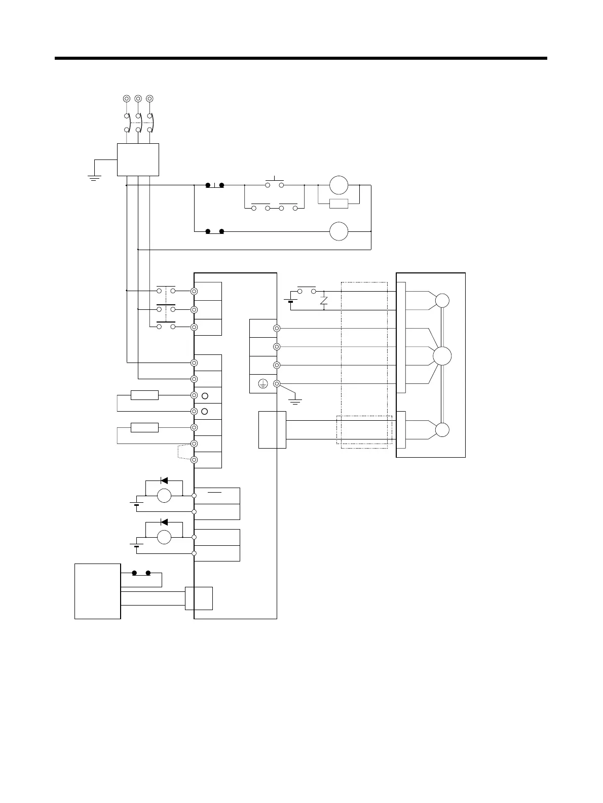
■ Three-phase Input: R7D-AP08H
Three-phase 200/230 V AC, 50/60 Hz
Noise filter (See note 1.)
Main-circuit power supply
Main-circuit contactor (See note 2.)
Surge killer (See note 2.)
Servo error display
Class D ground
(Class 3 ground:
100 Ω or less)
Class D ground
(Class 3 ground:
100 Ω or less)
User
control
device
Control cable
DC Reactor
Note 1. Recommended product in
3-2-4 Wiring for Noise Resistance.
2. Recommended relay: MY Relay (24 V), by OMRON.
3. An R88A-RR22047S External Regeneration Resistor may be connected.
Connect if the regenerative energy exceeds the individual Servo Driver's
regenerative capacity. Also, connect the thermal switch
output so that the power supply will be turned OFF when open.
4. If an External Regeneration Resistor is to be connected,
remove the short bar between B2 and B3.
5. When either the main-circuit power supply or the control-circuit
power supply is OFF, the dynamic brake will operate.
SMARTSTEP A-series Servo Driver SMARTSTEP A-series Servomotor
RT
NFB
S
123
456
E
NF
OFF
X
ON
1MC X
1MC
PL
L1
L2
1MC
W
V
U
B
E
M
CN2
Servomotor cable
24 V DC
XB
CN1
X
ALMCOM
ALM34
35
X
24 V DC
CN1
(See note 2.)
OGND
BKIR7
10
24 V DC
CN1
XB
L1C
L3
L2C
1
2
B1
B2
B3
(See note 4.)
External Regeneration Resistor
(See note 3.)
+
+
 Loading...


