Chapter 2
2-29
Standard Models and Specifications
● Positioning Completed Output (8: INP)
The INP signal turns ON when the number of accumulated pulses in the deviation counter is less
than Pn500 (positioning completed range).
● Brake Interlock Output (7: BKIR)
External brake timing signals are output.
2-3-5 Encoder Input Connector Specifications (CN2)
● CN2 Connectors Used (14P)
Servo Driver receptacle: 10214-52A2JL (Sumitomo 3M)
Cable solder plug: 10114-3000VE (Sumitomo 3M)
Cable case: 10314-52A0-008 (Sumitomo 3M)
2-3-6 Communications Connector Specifications (CN3)
● CN3 Connectors Used (8P)
Servo Driver receptacle: HR12-10R-8 SDL (Hirose Electric)
Cable connector: HR212-10P-8P (Hirose Electric)
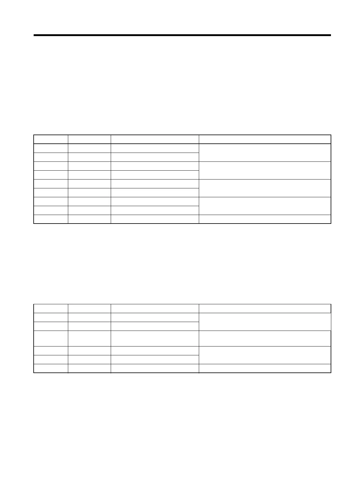
Pin No. Symbol Signal name Function/Interface
1, 2, 3 E0V Encoder power supply GND Power supply outlet for encoder: 5 V, 180 mA
4, 5, 6 E5V Encoder power supply +5 V
8 S+ Encoder + phase-S input Line driver input (conforming to EIARS-422A)
(Input impedance: 300
Ω±5%)
9 S– Encoder – phase-S input
10 A+ Encoder + phase-A input Line driver input (conforming to EIARS-422A)
(Input impedance: 300
Ω±5%)
11 A– Encoder – phase-A input
12 B+ Encoder + phase-B input Line driver input (conforming to EIARS-422A)
(Input impedance: 300
Ω±5%)
13 B– Encoder – phase-B input
Shell FG Shield ground Cable shield ground
Pin No. Symbol Signal name Function/Interface
1 /TXD Transmission data
Transmission data, RS-232C output
Reception data, RS-232C input
2 /RXD Reception data
3 PRMU Unit switching This is the switching terminal for a Parameter
Unit or personal computer.
7 +5V +5 V output This is the +5-V power supply output to the
Parameter Unit.
8 GND Ground
Shell FG Shield ground Cable shield ground
 Loading...


