Chapter 4
4-5
Operation
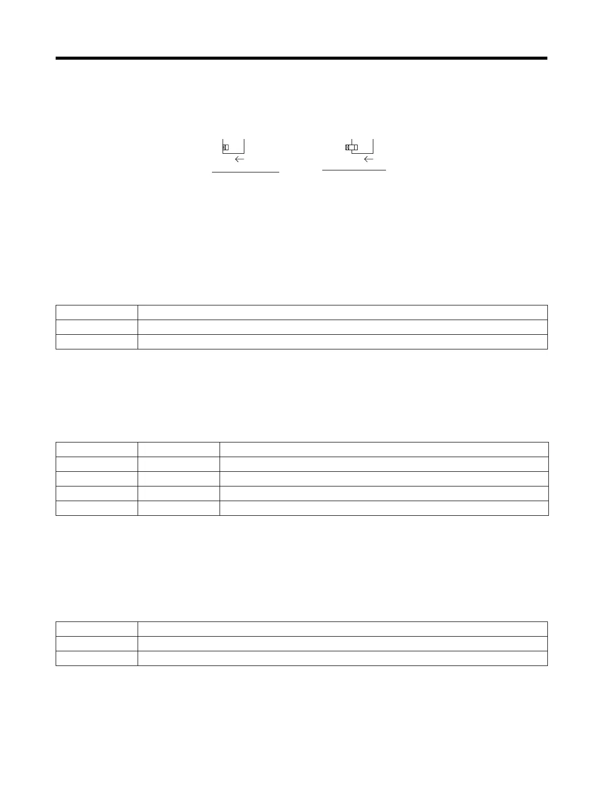
■ Turning Function Switches ON and OFF
The default setting for all function switches is OFF. Use a thin-blade non-conductive ceramic screw-
driver or equivalent to turn the switches ON and OFF. In the following diagrams, the left diagram
shows a switch turned OFF, and the right diagram a switch turned ON.
4-2-2 Setting Function Switches
■ Switch/Parameter Switch (Switch 6)
Switch 6 sets whether the Servo Driver is to be operated using the function switches, or using the
parameter settings.
Note Here, settings will be performed using the function switches, so turn OFF switch 6.
■ Resolution Setting (Switches 4 and 5)
Switches 4 and 5 set the positioning resolution. When they are set to 1,000 (the default setting), the
Servomotor will rotate once for every 1,000 pulses that are input.
Note At 5,000 pulses/rotation = 3,000 r/min at 250 kpps command pulses
At 10,000 pulses/rotation = 1,500 r/min at 250 kpps command pulses
■ Command Pulse Input Setting (Switch 3)
Switch 3 sets whether the command pulse input uses 2 pulses (forward (CCW) and reverse (CW)
pulses) or a 1 pulse (feed pulse (PULS) and a forward/reverse signal (SIGN)).
Note Set according to the pulse output form of the Position Controller.
Switch 6 Switch/parameter switch
OFF
Function switches are enabled. (Enables switches 1 to 5.)
ON
Parameter settings are enabled.
Switch 5 Switch 4 Resolution setting
OFF OFF 1,000 pulses/rotation (0.36°/step)
OFF ON 10,000 pulses/rotation (0.036°/step)
ON OFF 500 pulses/rotation (0.72°/step)
ON ON 5,000 pulses/rotation (0.072°/step)
Switch 3 Command pulse input setting
OFF Forward pulse (CCW)/reverse pulse (CW) input (Positive logic)
ON Feed pulse (PULS) forward/reverse signal (SIGN) input
1
1
O
N
O
N
Switch turned OFF
Switch turned ON
 Loading...


