Chapter 2
2-28
Standard Models and Specifications
● + Deviation Counter Reset (5: +ECRST)
– Deviation Counter Reset (6: –ECRST)
The content of the deviation counter will be reset when the deviation counter reset signal turns ON
and the position loop will be disabled. Input the reset signal for 20
µs minimum. The counter will not
be reset if the signal is too short.
● RUN Command Input (14: RUN)
This is the input that turns ON the power drive circuit for the main circuit of the Servo Driver. If this
signal is not input (i.e., servo-OFF status), the Servomotor cannot operate except for JOG opera-
tions.
● Alarm Reset (18: RESET)
This is the external reset signal input for the alarm. Remove the cause of the alarm and then restart
operation. Turn OFF the RUN command before inputting the reset signal. It can be dangerous to
input the reset signal while the RUN command is ON.
■ Control Output Details
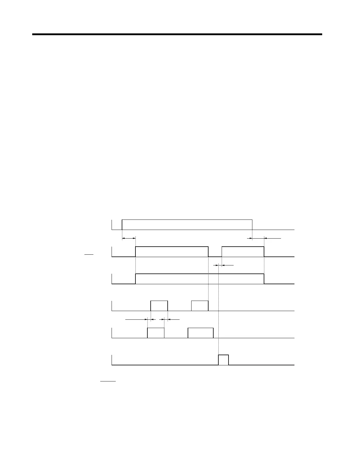
● Control Output Sequence
● Alarm Output (34: ALM)
Alarm Output Ground (35: ALMCOM)
When the Servo Driver detects an error, outputs are turned OFF. This output is OFF at the time of
powering up, and turns ON when the initial processing is completed.
Power supply input
(L1C, LC2, L1, L2, (L3))
Alarm output
(ALM)
Brake interlock output
(BKIR)
RUN command input
(RUN)
Alarm reset input
(RESET)
2 ms
0 to 35 ms
300 ms
Positioning completed output
(INP)
Approx. 2 s
ON
OFF
ON
OFF
ON
OFF
ON
OFF
ON
OFF
ON
OFF
2 ms
 Loading...


