Chapter 4
4-30
Operation
■ Parameters Requiring Settings
Note 1. Set within the range 0.01 ≤ G1/G2 ≤ 100.
Note 2. These parameters become effective when the power is turned ON again after having been
turned OFF. (Check to see that the LED display has gone OFF.)
Note 3. With the default setting (G1/G2 = 4), the Servomotor will rotate once when 2,000 pulses are
input.
Note 4. One position deviation (deviation counter) display and positioning completed range pulse
make one input pulse. (This is called a command unit.)
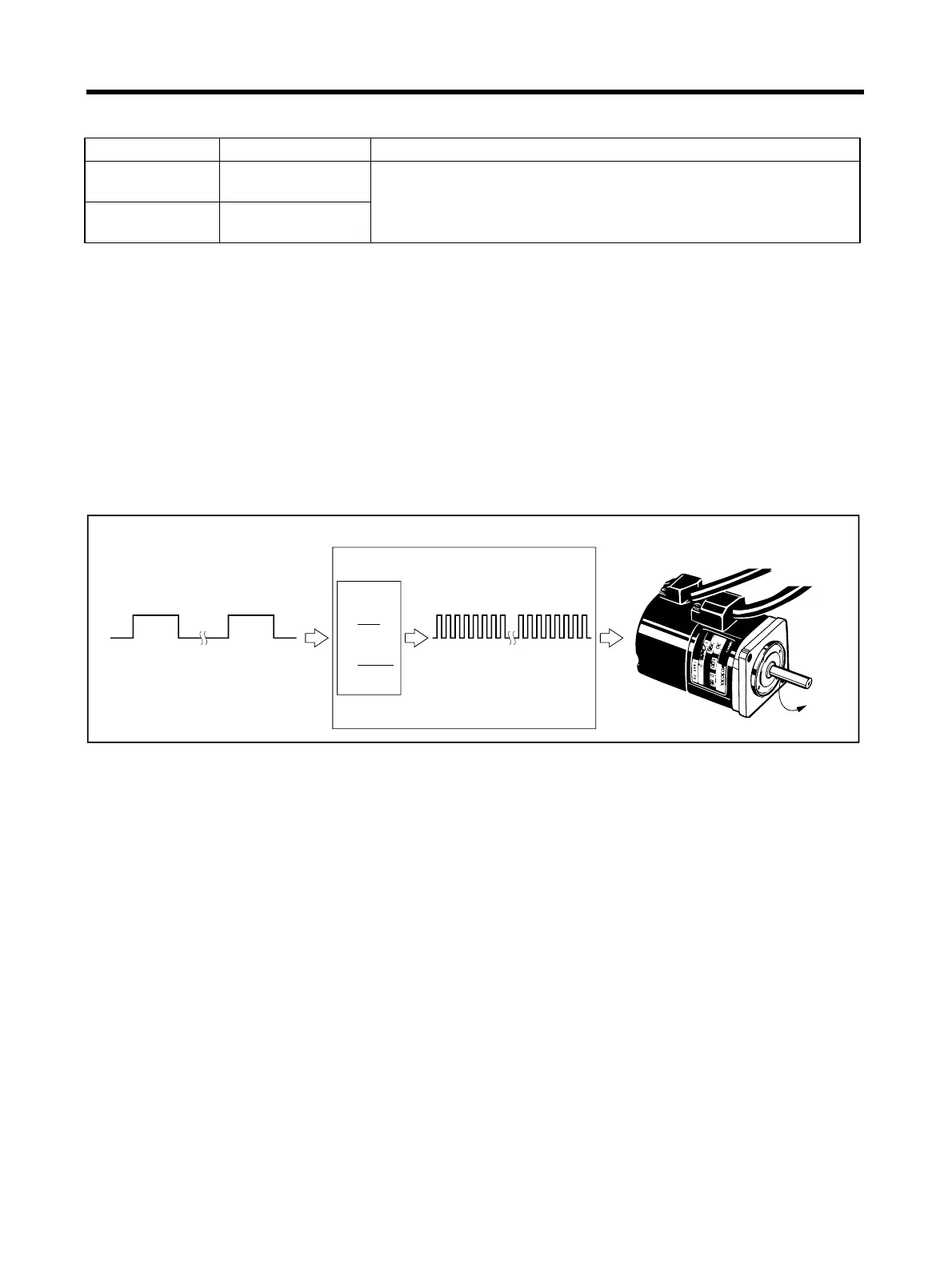
■ Operation
• When set to G1/G2 = 8,000/1,000, operation is the same as for a 1,000-pulses/rotation Servomotor.
Parameter No. Parameter name Explanation
Pn202 Electronic gear ratio
G1 (numerator)
Set the pulse rate for the command pulse and Servomotor travel dis-
tance. When G1/G2 = 1, if the pulse (encoder resolution
× 4) is
input, the Servomotor will rotate once (i.e., the internal driver will
rotate
× 4). (See note 1.)
Pn203 Electronic gear ratio
G2 (denominator)
1,000 pulses
Electronic
gear
8,000 pulses
Servo Driver
Servomotor
(Encoder resolution:
2,000 pulses/rotation)
1 rotation (2,000 pulses)
G1
G2
8000
1000
=
 Loading...


