Chapter 2
2-33
Standard Models and Specifications
Note 1. *The values for items marked by asterisks are the values at an armature winding tempera-
ture of 100
°C, combined with the Servo Driver. Other values are at normal conditions (20°C,
65%). The momentary maximum torque shown above indicates the standard value.
Note 2. The brakes are the non-excitation operation type (released when excitation voltage is ap-
plied).
Note 3. The operation time is the measured value (reference value) with a surge killer (CR50500, by
Okaya Electric Industries co. LTD) inserted.
Note 4. The allowable radial and thrust loads are the values determined for a service life of 20,000
hours at normal operating temperatures.
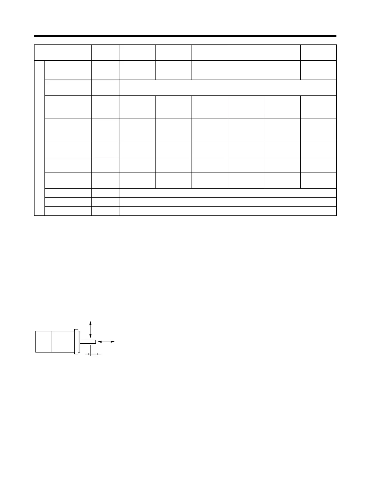
Note 5. The value indicated for the allowable radial load is for the positions shown in the diagrams
following the next table.
Brake specifications
Brake inertia
kg
⋅m
2
(GD
2
/4)
8.5
× 10
–7
8.5 × 10
–7
8.5 × 10
–7
6.4 × 10
–6
6.4 × 10
–6
1.71 × 10
–5
Excitation volt-
age
V24 V DC ±10%
Power con-
sumption (at
20
°C)
W666777.7
Current con-
sumption (at
20
°C)
A 0.25 0.25 0.25 0.29 0.29 0.32
Static friction
torque
N
⋅m 0.2 min. 0.2 min. 0.34 min. 1.47 min. 1.47 min. 2.45 min.
Attraction time
(See note 3.)
ms 30 max. 30 max. 30 max. 60 max. 60 max. 60 max.
Release time
(See note 3.)
ms 60 max. 60 max. 60 max. 20 max. 20 max. 20 max.
Backlash 1
° (reference value)
Rating – Continuous
Insulation grade – Type F
Item Unit R7M-
A03030
R7M-
A05030
R7M-
A10030
R7M-
A20030
R7M-
A40030
R7M-
A75030
Radial load
Thrust load
5 mm
 Loading...


