Chapter 2
2-61
Standard Models and Specifications
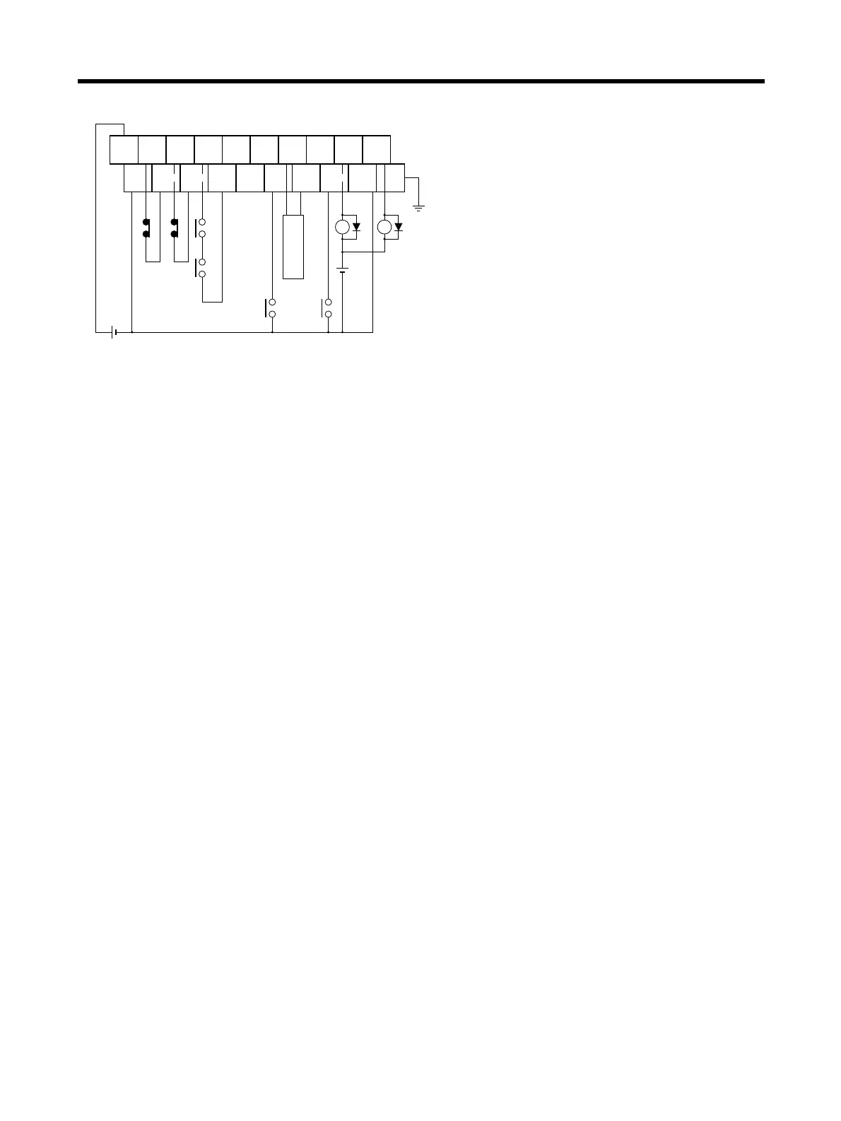
● Wiring
+24 V
0 V
CW CCW RUN INP ALM BKIR10
0
19
9
CW CCW
Com-
mon
ECRST
Z
RESET ALMCOM
FG
24 V DC
X1 XB
24 V DC
(See note 3.)
(See note 2.)
(See
note 1.)
X1
Com-
mon
(See
note 1.)
CQM1 Input
Unit
Note 1. If these signals are input, the CQM1 output pulse can be input into the High-
speed Counter.
Note 2. Input this output signal to the CQM1 Input Unit.
Note 3. The XB contact is used to turn ON/OFF the electromagnetic brake.
Note 4. Phase Z is an open-collector output.
Note 5. Do not connect unused terminals.
Note 6. The 0-V terminal is internally connected to the common terminals.
Note 7. The following crimp terminal is applicable: R1.25-3 (round with open end).
 Loading...


