Chapter 2
2-67
Standard Models and Specifications
● Terminal Block Connection
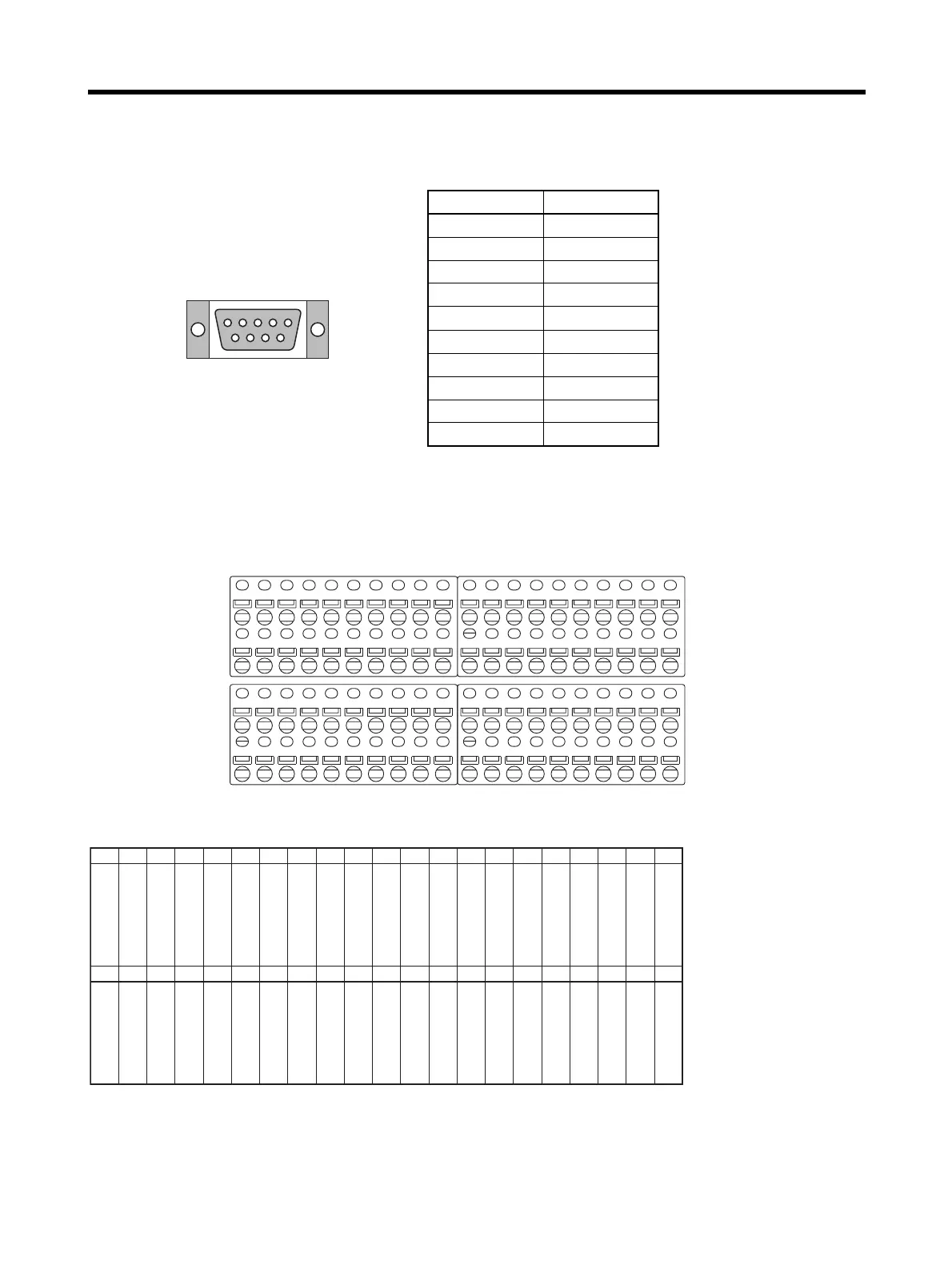
1. RS-422 Connector
2. Screwless Clamp Terminal Blocks
Use the screwless clamp terminal blocks to wire controller general-purpose I/O and Servo Driver
control signals.
Upper Terminal Block Pin Arrangement
Connect to an RS-422 line. Pin No. Signal name
1TXD
−
2TXD+
3 ---
4 ---
5 ---
6RXD
−
7 ---
8RXD+
9 ---
Shell FG
60
Upper terminal block
Lower terminal block
0
79
19
0 1 2 3 4 5 6 7 8 9
0 1 2 3 4 5 6 7 8 9
0 1 2 3 4 5 6 7 8 9
0 1 2 3 4 5 6 7 8 9
0 1 2 3 4 5 6 7 8 9
0 1 2 3 4 5 6 7 8 9
0 1 2 3 4 5 6 7 8 9
0 1 2 3 4 5 6 7 8 9
Signal name
Signal name
5 V (See note 1.)
Latch signal input 1
Latch signal input 2
CNT1 A phase LD
+ input
CNT1 B phase LD
+ input
Servo Driver #1
Z phase LD+ output
Voltage input (+)
Servo Driver #1 ALM
---
IN4
IN5
IN6
IN7
---
Servo Driver #1 RUN
Servo Driver #1
RESET
Servo Driver #1
ECRST
---
TXD+
RXD+
No.
No.
60 61 62 63
Latch signal 1
common (0 V)
Latch signal 2
common (0 V)
CNT1 A phase LD−
CNT1 B phase LD−
Servo Driver #1
Z phase LD−
Voltage input (−)
Common (0 V)
---
Common (0 V)
Common (0 V)
Common (0 V)
Common (0 V)
---
TXD−
RXD−
OUT0
OUT1
OUT2
OUT3
0 V
64 65 66 67 68 69 70 71 72 73 74 75 76 77 78 79
40 41 42 43 44 45 46 47 48 49 50 51 52 53 54 55 56 57 58 59
 Loading...


