75
Installation Section 2-2
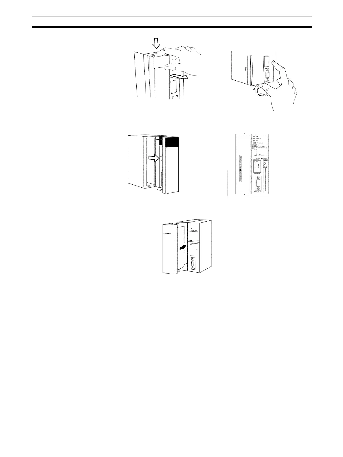
2. Remove the Inner Board compartment cover.
3. Insert the Serial Communications Board.
Note Be sure to tighten the mounting screw on the bottom side securely to the tight-
ening torque of 0.4 N⋅m.
Precaution When
Handling the Loop Control
Board
• Always turn OFF the power to the PLC before removing the CS1W-LCB01
or CS1W-LCB05 Loop Control Board.
• If the RS-232C port is not being used, leave the dust cover attached to the
port during operation.
2-2-3 Handling Analog Input/Output Units
Note The Loop Controller is used in combination with an Analog Input/Output Unit.
Note the following points when handling the Analog Input/Output Unit:
• Before starting running of the Loop Controller, make sure that the Analog
Input/Output Unit is correctly mounted on the same PLC Unit. Even if run-
ning of the Loop Controller is started without the Analog Input/Output Unit
mounted on the same PLC Unit, warning messages to this effect are not
displayed on the screens of CX-Process Tool.
• The unit number set on the front panel of the Analog Input/Output Unit
must be set to the same as the unit number specified in the Field Terminal
block. If unit numbers should differ, reading and writing will be performed
Press the top catch. Press the bottom catch.
Inner Board Connector

 Loading...


