66
Basic Procedure for Using the Loop Controller Section 1-5
1-5 Basic Procedure for Using the Loop Controller
This section describes the basic procedure for using the Loop Controller.
For examples of actual procedures, see Section 4 Simple Examples of Use.
1. Design
1,2,3... 1. Prepare an instrumentation drawing.
See this Section (for understanding which functions can be used on the
Loop Controller).
See Section 5 Examples of Function Block Combinations.
Analog
signal set-
ting/selec-
tion
Setting of analog signals to specified
ITEMs under certain conditions
Use the Variable ITEM Setting block (Block
Model 171).
3-1 Configuration of Function
Blocks and Function Block Refer-
ence Manual
Selection of one of multiple analog sig-
nals and transmission of that analog sig-
nal as an analog signal
Use the Input Selector block (Block Model
162).
Function Block Reference Manual
Selection of the maximum value from
multiple analog signals and transmission
of that maximum value as an analog sig-
nal
Use the Rank Selector block (Block Model
161).
Selection of the minimum value from mul-
tiple analog signals and transmission of
that minimum value as an analog signal
Selection of the nth largest value from
multiple analog signals and transmission
of the signal as an analog signal
Switching of sensors on a different mea-
suring system or measurement target
Use the 3-input Selector block (Block Model
163).
Switching of operation nodes on a differ-
ent measuring system or measurement
target
Use the 3-output Selector block (Block
Model 164).
Changing two settings with a ramp (e.g.,
opening and closing valves)
Use the Ramped Switch block (Model Block
167).
Converting ranges of analog signals
merely by setting values for 0% and
100% inputs and 0% and 100% outputs
Use the Range Conversion block (Block
Model 127).
Comparison of constant and analog sig-
nals
Use the Constant Comparator block (Block
Model 202).
Comparison of two analog signals Use the Variable Comparator block (Block
Model 203).
Manipula-
tion/moni-
tor/control
of special
external
control tar-
get
Manipulation and monitoring of ON/OFF
valve with open/close limit switches
Use the ON/OFF Valve Manipulator block
(Block Model 221) and Switch Meter block
(Block Model 225).
Manipulation and monitoring of motors Use the Motor Manipulator block (Block
Model 222) and Switch Meter block (Block
Model 225).
Manipulation and monitoring of reversible
motors
Use the Reversible Motor Manipulator block
(Block Model 223).
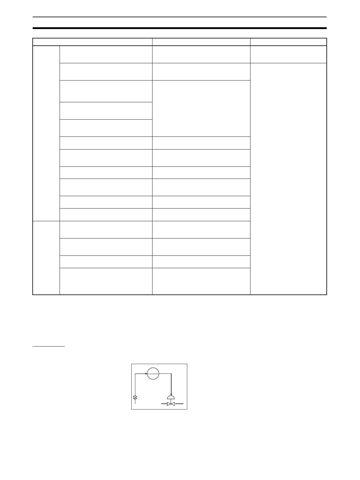
Manipulation of a electric positional-pro-
portional motor as the control target
Use the Basic PID (Block Model 011)/
Advanced PID block (Block Model 012) and
Motor Opening Manipulator block (Block
Model 224) and Switch Meter block (Block
Model 225).
To perform this specific operation Perform the following See page:
PIDPV MV

 Loading...


