51
Specifications Section 1-3
1-3 Specifications
1-3-1 General Specifications
These specifications conform to the general specifications of the SYSMAC
CS-series.
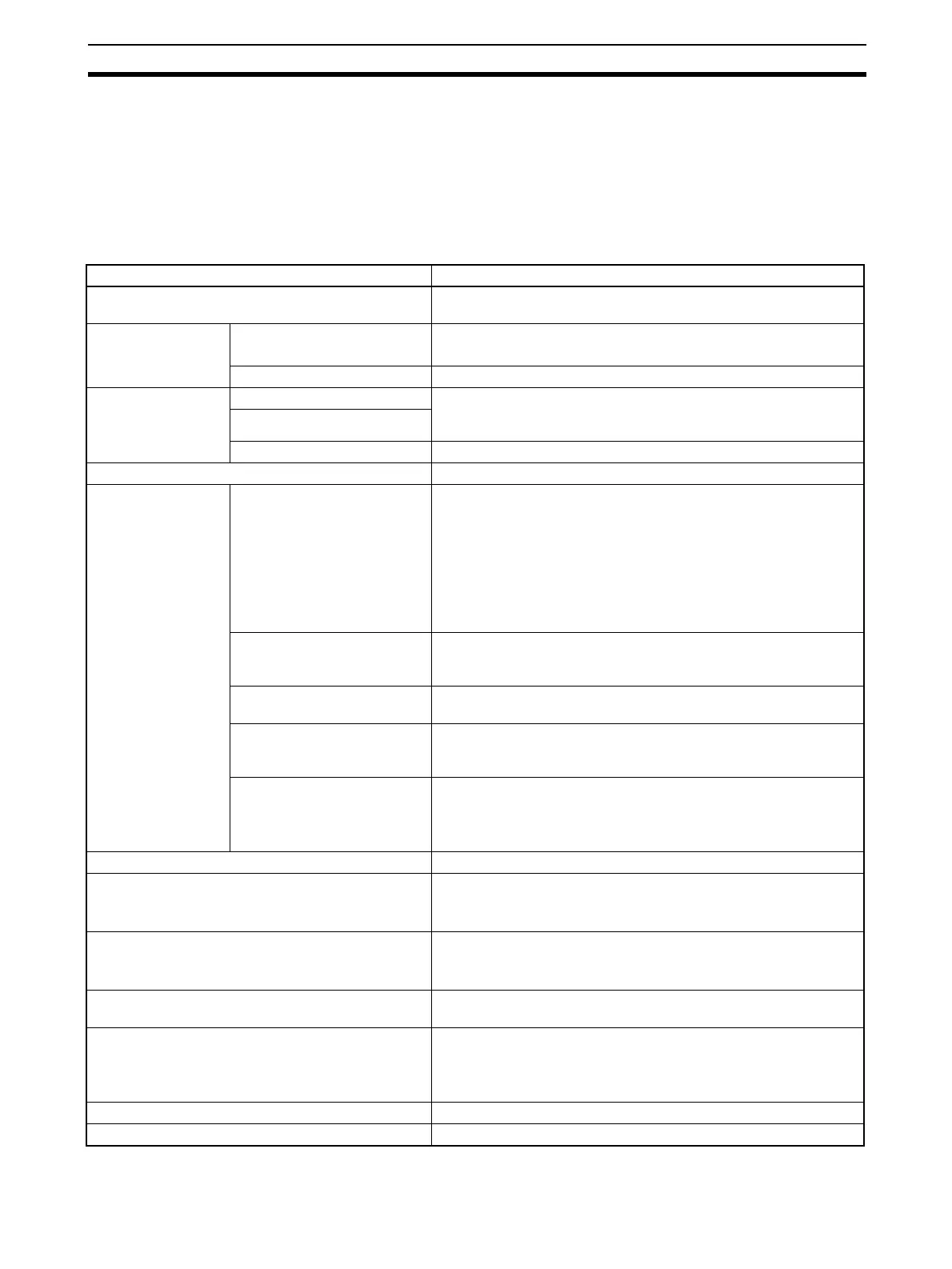
1-3-2 Specifications
Item Specification
Product name Loop Control Board, Process-control CPU Unit, Loop-control CPU
Unit
Model numbers Non-duplex Inner Boards Loop Control Board: CS1W-LCB01 and CS1W-LCB05
Loop-control CPU Unit: CJ1G-CPU@@P
Duplex Inner Boards Process-control CPU Unit: CS1D-CPU@@P
Applicable CPU
Units
CS1W-LCB01 CS1G/H-CPU@@H
CS1D-CPU@@S (supported for Loop Control Board version 1.5 or
later only)
CS1W-LCB05
Process-control CPU Unit CS1D-CPU Unit with built-in Duplex Loop Controller
Unit classification CS-series Inner Board
Data exchange
method with CPU
Unit
Words in Auxiliary Area in
CPU Unit
Loop Controller → CPU Unit:
Operation status, PV error input ON, MV error input ON, occur-
rence of execution error, function block database error, cold start
ready for hot start command, flash memory backup in progress,
function blocks changed, etc.
CPU Unit → Loop Controller:
Hot/cold start command at power ON (Not supported for CS1D-
CPU@@P. )
Allocated Words to Inner
Board in CIO Area of CPU
Unit
Not used
Allocated Words to Inner
Board in DM Area of CPU Unit
Not used
User allocations in I/O mem-
ory
User memory tables used to allocate function block ITEM data for
user-specified memory in the CPU Unit (CIO, Work, HR, DM, or
EM Area (bank 0, but also banks 1 to 12 for Ver. 3.0 or later)).
EM Area (bank number) allo-
cations (for SCADA software)
HMI function used allocate function block ITEM data for Control,
Operation, External Controller, and System Common blocks in the
specified bank of the EM Area in the CPU Unit.
The real PV in calibration mode can be allocated (Ver. 3.0 or later).
Setting None
Indicators Loop-control CPU Units: 2 LEDs (RUN and ready)
Other Controllers:
3 LEDs: RUN, ready, and communications port send/receive
Front panel interface RS-232C port x 1 (Used for connection to ES100X Controller.)
(Not supported by Loop-control CPU Units and Process-control
CPU Units.)
Super capacitor backup data All function block data (including Step Ladder Program com-
mands), stored error log data
Super capacitor backup time CS Series (CS1W-LCB01/05 or CS1D-CPU@@P): 24 hours at
25°C (life shortened by use at higher temperatures)
CJ Series (CJ1G-CPU@@P): 5 min at 25°C (Backed up by the Bat-
tery in the CPU Unit.)
Data stored in flash memory Function block data
Backup from RAM to flash memory Executed from CX-Process Tool (as required).

 Loading...


