132
Description of Operation Section 3-2
Note The LCB@@s do not support the automatic operation cycle switching function
of the Loop Control Units. The High Load Alarm Flag (A42408), however, will
turn ON if the LCB load rate exceeds 80% for 6 seconds. If this bit turns ON,
use longer operation cycles or add Loop Control Units to distribute process-
ing.
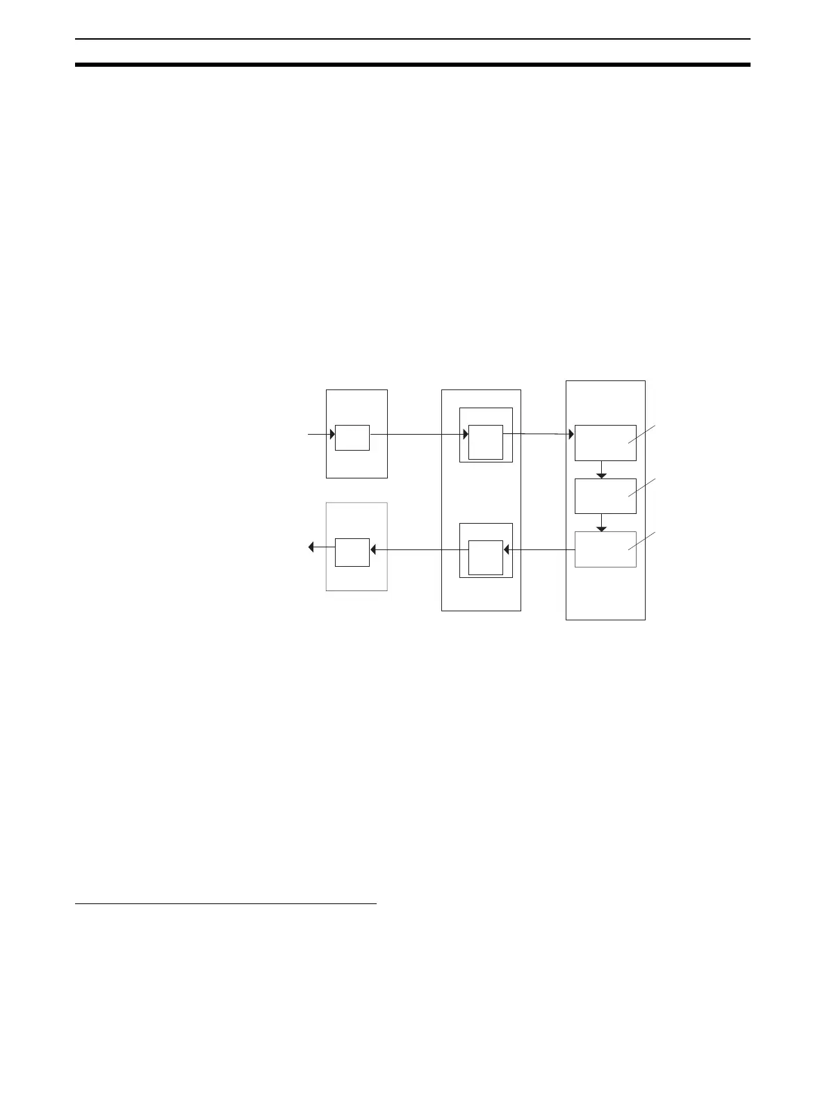
3-2-19 External I/O Response Cycle on the Overall System
The Loop Controller exchanges field I/O values (analog input values, analog
output values, contact inputs and contact outputs) with external Units by the
following method.
1,2,3... 1. The Analog Input/Output Unit or the Basic I/O Unit refresh the I/O memory
on the CPU Unit.
2. The Loop Controller exchanges data allocated to I/O memory on the CPU
Unit according to the operation cycle of each function block.
Example Data exchange of analog input, PID operation and analog output
The external I/O response time in the overall system (simply called “the exter-
nal I/O response time” from here on) refers to the time from when the analog
input data is converted and the Analog Input Unit reads the analog input value
to when the PID operation is performed and the Analog Output Unit outputs
analog output value. This response time indicates the response of the overall
system.
Note The external I/O response time is equivalent to twice the input sampling cycle
(or operation cycle) on a general controller. For this reason, when designing
the system, calculate the external I/O response time according to the formu-
lae shown below, and study whether or not there will be any problem with con-
trol with the target application. In particular, study whether or not there will be
any problem in controllability of PID control in the case of fast-response con-
trol targets, such as pressure or flowrate. Calculate the external I/O response
time using the methods described in the following sections.
Maximum External I/O Response Time
CS1W-LCB01 and CS1W-
LCB05 Loop Control
Boards and Loop-control
CPU Units (CJ1G-
CPU@@P)
The maximum external I/O response time is calculated as follows:
2 x A/D conversion time + (2 x CY) + (2 x T) + 2 x D/A conversion time
where,
CY: Cycle time of the CPU Unit
T: Operation cycle
Analog Input Unit
Loop Controller
CPU Unit
I/O refreshing
I/O memory
Log input
Function block
Analog Input
block
A/D
conversion
Analog
input
converted
value
Execution
cycle 0.2 s
Analog Output
Unit
Log input
D/A
conversion
I/O refreshing
I/O memory
Analog
input
converted
value
PID block
Execution
cycle 0.2 s
Analog output
block
Execution
cycle 0.2 s
Operation
cycle
Operation
cycle

 Loading...


