23
Outline Section 1-1
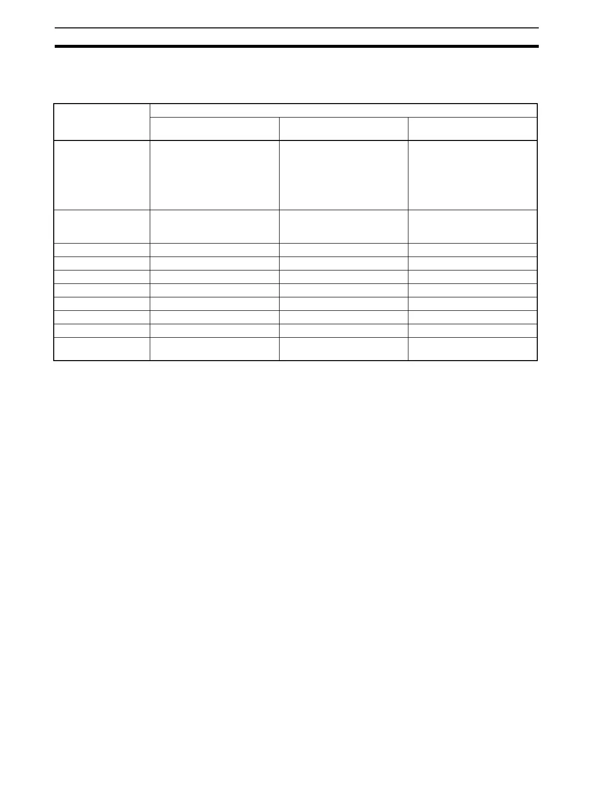
Note Relationship between CPU Unit I/O Memory and Loop Controller
The Loop Controller can read from and write to CPU Unit I/O memory by the
methods indicated in the following table.
1-1-12 Internal Mechanism of Loop Controllers
The following describes the internal mechanism of the Loop Controller.
• Function block data and error log data are backed up by a super capacitor
in RAM. During actual operation, the Loop Controller uses the data in
RAM.
• Function block data is prepared and downloaded to RAM and flash mem-
ory in the Loop Controller from CX-Process Tool running on the computer.
From the CX-Process Tool, you can transfer data between RAM and flash
memory whenever necessary.
• Error log data is stored in flash memory can be read using the READ
ERROR LOG FINS command (command code 2102 Hex).
• In the default state, function block data is not stored on the Loop Control-
ler. Function block data must be downloaded from a computer to RAM
and flash memory in the Loop Controller before the Loop Controller can
be run.
Data direction Purpose of data on Loop Controller
Loop Controller
↔ CPU Unit
Loop Controller
↔ CPU Unit
Loop Controller
→ CPU Unit
I/O memory area type
on CPU Unit
Reading or writing at CPU Unit
Terminals, Expanded CPU Unit
Terminals, or Send/Receive All
Blocks
❍ : Possible,
---: Impossible
Reading or writing at field ter-
minals
Writing using the Auxiliary
Area
CIO ❍ Reading/writing of CIO area on
corresponding Unit at field ter-
minals
Notifying of Loop Controller
status
Work Area (W) ❍ --- ---
Holding Area (H) ❍ --- ---
Auxiliary Area --- --- ---
TR Area --- --- ---
Timer --- --- ---
Counter --- --- ---
Data Memory Area (D) ❍ --- ---
Extended Data Mem-
ory Area (E)
❍ (bank No.0 only) --- ---
 Loading...


