83
Configuration of Function Blocks Section 3-1
Note (a) Which function block data is written to or which function block
data is read from is determined by the block address for each
ITEM.
(b) Block Model and Block Address
The “Block Model” is a number for specifying the type of block and
is not set by the user in CX-Process Tool. Be careful not to confuse
the Block Model with the “block address” that is used as the ad-
dress for execution that is set by the user.
2. Wire analog signals (or accumulated value signals) between function
blocks. (See 3-1-5 Connecting Function Blocks described later.)
3. Set ITEM data other than the analog signals.
(c) Wiring of analog signals (or accumulated value signals) between
function blocks is also possible by setting the data of each ITEM.
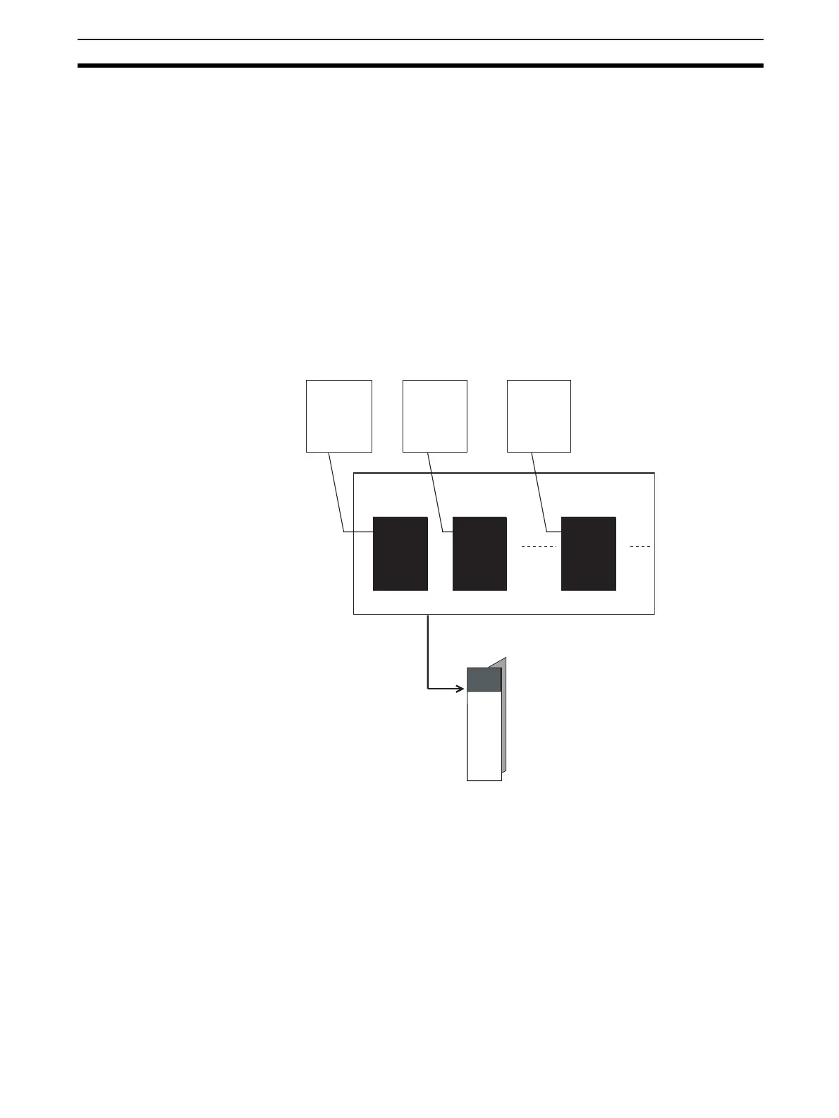
4. Download the function block data sheets to the Loop Controller.
Basic PID
(Block Mode 011)
Function block
Example:
Block address
001
Allocation
Basic PID
(Block Mode 011)
Function block
Example:
Block address
002
Allocation
Square Root
(Block Model 131)
Function block
Example:
Block address
100
Allocation
Function block data sheet (file extension.ist)
Download
Loop Controller

 Loading...


