EasyManua.ls Logo

Omron SYSMAC NX-CIF105 User Manual

Omron SYSMAC NX-CIF105
232 pages
To Next Page IconTo Next Page
To Previous Page IconTo Previous Page
Page #125 background imageLoading...
Page #125 background image
7 - 21
7 Serial Communications
NX-series Communications Interface Units User’s Manual (W540)
7-4 Examples of Communications between CPU Unit or Communications Master and CIF Unit
7
7-4-4 Example for a Parity Error during Data Reception
This section gives an example of a parity error in the third character when a 6-byte string (123456) was
received.
Here, we will assume that the input notification data and output notific
ation data are in the following sta-
tus before the data is received.
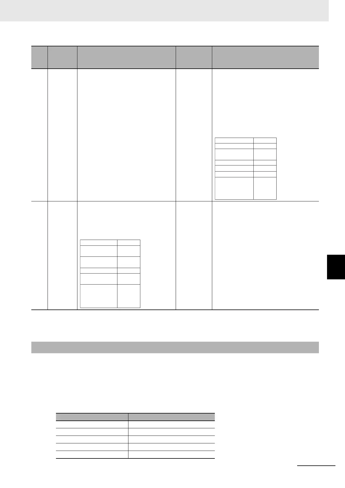
Input Notification Data
7 •Confirm-
ing
sending
of
ABCD
Notifica-
tion of
end
de
tec-
tion
The communications master receives
th
e inp
ut notification data given on the
right.
The communications master knows
th
at
the CIF Unit sent ABCD to the
serial line because the Send Com-
pleted Toggle Bit in the Port Status in
th
e input notification data changed.
The communications master knows
th
at
the CIF Unit detected the end of
the receive data because the End
Detected in the Port Status in the input
notification data is TRUE.
The CIF Unit inputs the following input
notificatio
n data and
tells the CPU Unit or
communications master that ABCD was
sent to the serial line.
At the same time, the CIF Unit tells the
CPU Unit or co
mmunications master that
the end of the receive data was detected.
8 Input
re
sponse
for end
detection
The communications master outputs the
following output notification
data to tell
the CIF Unit that notification of the detec-
tion of the end of the receive data was
receiv
ed normally.
The CIF Unit receives the output notifica-
tion data given on the left.
The CIF Unit knows that the CPU Unit or
communica
ti
ons master has normally
received the notification of the detection of
the end of the receive data because the
Input SID Response in the output notifica-
tion data is 04 hex.
*1. : Output notification data is output from the CPU Unit or communications master to the CIF Unit.
: Input notification data is input from the CIF Unit to the CPU Unit or communications master.
*2. In this example, the end is not detected when the CIF Unit receives ABCD.
7-4-4 Example for a Parity Error during Data Reception
NX object name Value
Port Status 8012 hex
Input SID 04 hex
Output SID Response 03 hex
Input Data Type 2000 hex
Input Sub Info 0000 hex
Step Process
CPU Unit or communications master
processing
Communi-
cations
direction
*1
CIF Unit processing
Incremented.
The Send
Completed Toggle
Bit changed.
End was detected.
0 bytes
This is the final
receive data.
8012 hex
04 hex
03 hex
2000 hex
0000 hex
0000 hex
00 hex,
00 hex,
00 hex,
00 hex
Input Data 01
Port Status
Input SID
Output SID
Response
Input Data Type
Input Sub Info
Input Data Length
03 hex
04 hex
0000 hex
0000 hex
0000 hex
00 hex,
00 hex,
00 hex,
00 hex
Set the Input
SID.
Output SID
Input SID
Response
Output Data
Type
Output Sub Info
Output Data
Length
Output Data 01

Table of Contents

Question and Answer IconNeed help?

Do you have a question about the Omron SYSMAC NX-CIF105 and is the answer not in the manual?

Omron SYSMAC NX-CIF105 Specifications

General IconGeneral
Number of Ports1
Port TypeRJ45
Operating Temperature0 to 55 °C
TypeCommunication Interface Unit
Compatible SeriesNX-series
Isolation Voltage500 VAC

Summary

Features and System Configuration

Features of Communications Interface Units

Details the features of the Communications Interface Units as Sysmac and NX devices.

System Configuration

Describes system configurations for connecting CIF Units to CPU Units or Coupler Units.

Unit Models, Functions, and Support Software

Outlines available CIF Unit models, their functions, and necessary support software.

Serial Communications Instructions for the CIF Units

Explains serial communication instructions for implementing no-protocol transfers.

Specifications and Application Procedures

Specifications

Provides general specifications and individual unit specifications for CIF Units.

Application Procedures

Details the procedures for setting up, wiring, and operating CIF Units.

Part Names and Functions

Part Names

Identifies and describes the physical parts of the CIF Units.

Indicators

Explains the indicators on the CIF Units and their operational meanings.

Installation and Wiring

Installing NX Units

Provides instructions for installing NX Units, including CIF Units.

Connecting the Power Supply and Ground Wires

Details how to connect power supply and ground wires to the CIF Units.

Wiring the Terminals

Explains how to wire the terminals on the CIF Units, including connector types.

Special Information

Precautions for Safe Use

Precautions on what to do and not to do to ensure safe usage.

Precautions for Correct Use

Precautions on what to do and not to do to ensure proper operation.

Safety Precautions

During Power Supply

Safety precautions related to the power supply.

Fail-safe Measures

Requirements for external fail-safe measures in the system.

Voltage and Current Inputs

Precautions regarding input voltage and current ranges.

Precautions for Safe Use

Installation

Safety precautions during the installation process.

Wiring

Safety guidelines for wiring communications cables.

Precautions for Correct Use

Storage, Mounting, and Wiring

Precautions for storing, mounting, and wiring Units correctly.

Regulations and Standards

Sections in this Manual

Features and System Configuration

Describes unit features and system configurations.

Specifications and Application Procedures

Provides specifications and application procedures.

Part Names and Functions

Details part names and functions of CIF Units.

Installation and Wiring

Covers installation and wiring procedures for CIF Units.

Troubleshooting

Provides error information and corrections.

I/O Data Specifications

Unit Settings

Serial Communications

Serial Line Monitor

Troubleshooting

How to Check for Errors

Methods for checking and identifying errors.

Checking for Errors with the Indicators

Using unit indicators to check for errors.

Checking for Errors and Troubleshooting on the Support Software

Troubleshooting errors using support software.

Resetting Errors

Procedures for resetting detected errors.

Troubleshooting Flowchart

A flowchart for the troubleshooting process.

Maintenance and Inspections

Related product manuals