3 Part Names and Functions
3 - 2
NX-series Communications Interface Units User’s Manual (W540)
3-1 Part Names
This section gives the names of the parts of the CIF Units and describes the functions of the parts.
This section gives the names of the parts of the NX-C
IF101 and NX-CIF105, and describes the func-
tions of the parts.
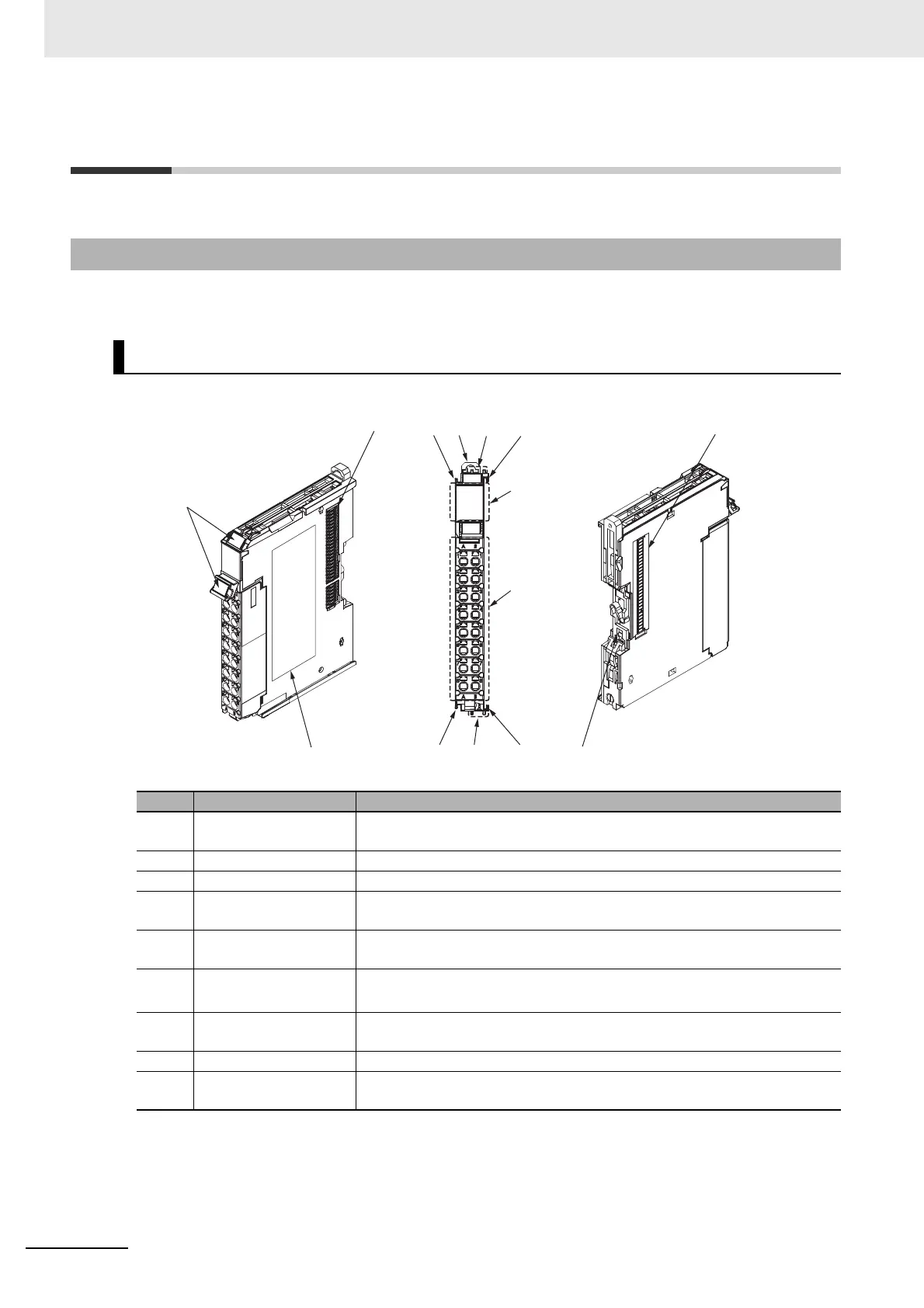
3-1-1 NX-CIF101 and NX-CIF105
Unit Parts
Letter Name Description
(A) Marker attachment loca-
tion
This is where the markers are attached. OMRON markers are pre-install
ed at
the factory. You can also install commercially available markers.
(B) NX bus connector This connector is used to connect each Unit.
(C) Unit hookup guides These guides are used to connect two Units.
(D) DIN Track mounting
hooks
Th
ese hooks are used to mount the NX Unit to a DIN Track.
(E) Protrusions for remov-
ing the Unit
These protrusions are to hold onto when you need to pull out the Unit.
(F) Indicators The indicators show the current operating status of the Unit.
Refer to 3-2 Indicators on page 3-5.
(G) T
erminal block This terminal block is used to connect the external serial communications
device.
(H) Unit specifications The specifications of the Unit are given here.
(I) DIN Track contact plate This plate is connected internally to
the functional ground terminal on the ter-
minal block.
(C)(D)
(H)
(G)
(F)
(C)
(A)
(E)
(C)
(I)
(E)
(C)
(B)
(B)
 Loading...