7 - 23
7 Serial Communications
NX-series Communications Interface Units User’s Manual (W540)
7-4 Examples of Communications between CPU Unit or Communications Master and CIF Unit
7
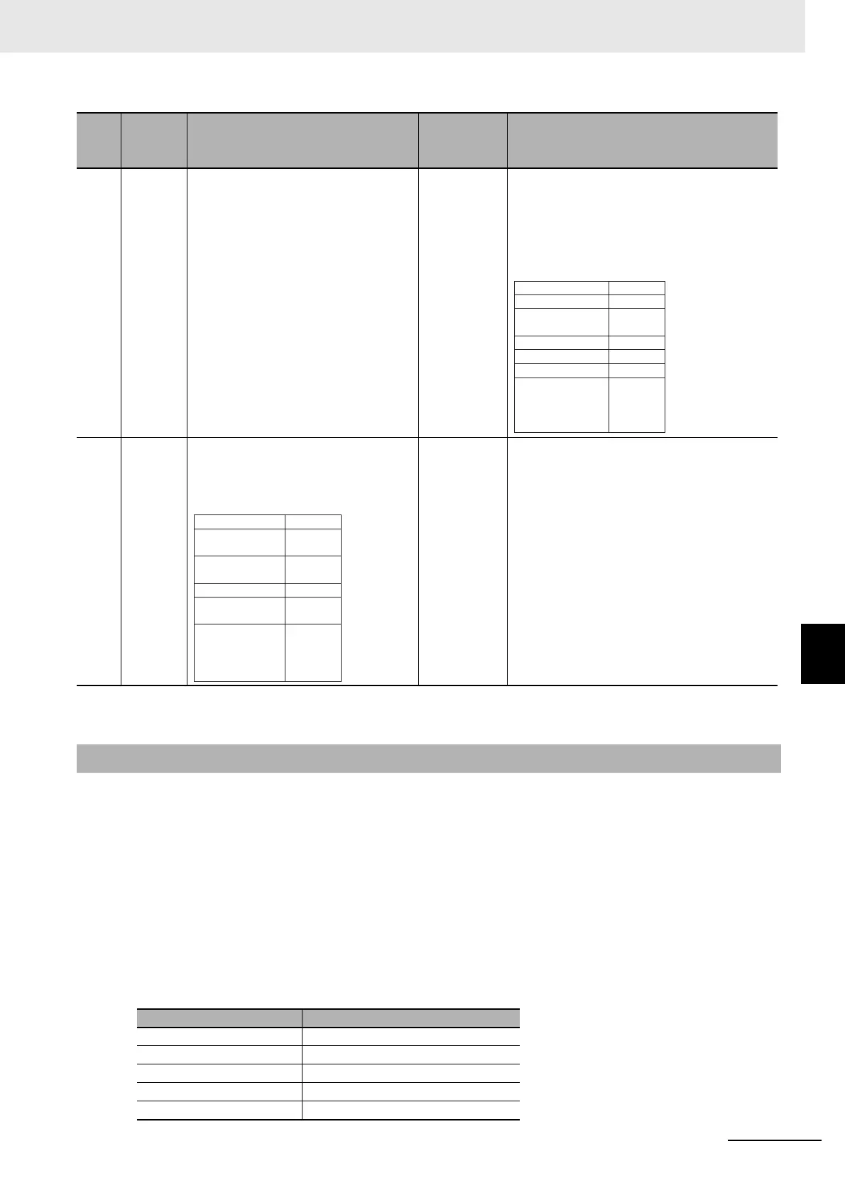
7-4-5 Example of Control Command Execution
This example executes a control command to restart a port.
In response to this
, the CPU Unit or communications master must initialize the value of the Output SID.
In this example, the value of the Output SID is initialized before the Restart Por
t control command is
executed in case an unexpected error, such as a communications error, occurs.
For a programming sample for this example, refer to A-4-2 Programming Sample 1: Restarting CIF Unit
Ports
on page A-32.
Here, we will assume that the input notification data and output notific
ation data are in the following sta-
tus before the control command is executed.
Input Notification Data
4 • Input-
ting
456
• Discard-
ing 456
• The communications master
receives the inp
ut notification data
given on the right.
• The communications master knows
th
at
the CIF Unit detected the end of
the receive data because the End
Detected in the Port Status in the
input notification data is TRUE.
• The communications master dis-
cards 456 because it is part of the
receive data
for which a parity error
occurred.
• The CIF Unit inputs the following input noti-
fication data to pass 456 to the CPU Unit or
communi
cations master.
•
At the same time, the CIF Unit tells the CPU
Unit or communica
tions master that the end
of the receive data was detected.
5 Input
response
fo
r 4
56
The communications master outputs
the following output notification data to
tell the CIF Unit that 456 was received
normally.
• The CIF Unit receives the output notification
da
ta given on the left.
• The CIF Unit knows that 456 was normally
recei
v
ed by the CPU Unit or communica-
tions master because the Input SID
Re
sp
onse in the output notification data is
06 hex.
*1. : Output notification data is output from the CPU Unit or communications master to the CIF Unit.
: Input notification data is input from the CIF Unit to the CPU Unit or communications master.
7-4-5 Example of Control Command Execution
NX object name Value
Port Status 0010 hex
Input SID 05 hex
Output SID Response 03 hex
Input Data Type 2000 hex
Input Sub Info 0000 hex
Step Process
CPU Unit or communications mas-
ter processing
Communi-
cations
direction
*1
CIF Unit processing
456
Incremented.
End was detected.
3 bytes
This is the final
receive data.
8012 hex
06 hex
03 hex
2000 hex
0000 hex
0003 hex
34 hex,
35 hex,
36 hex,
00 hex
Input Data 01
Port Status
Input SID
Output SID
Response
Input Data Type
Input Sub Info
Input Data Length
03 hex
06 hex
0000 hex
0000 hex
0000 hex
00 hex,
00 hex,
00 hex,
00 hex
Set the Input
SID.
Output SID
Input SID
Response
Output Data
Type
Output Sub Info
Output Data
Length
Output Data 01