3 Part Names and Functions
3 - 4
NX-series Communications Interface Units User’s Manual (W540)
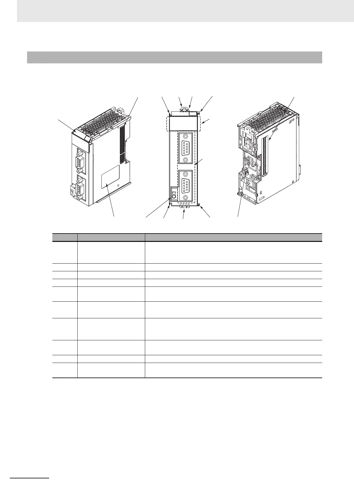
This section gives the names of the parts of the NX-CIF210, and describes the functions of the parts.
3-1-2 NX-CIF210
Letter Name Description
(A) Marker attachment loca-
tion
This is where the markers are attached. OMRON markers are
pre-installed
at the factory. You can also install commercially available
markers.
(B) NX bus connector This connector is used to connect each Unit.
(C) Unit hookup guides These guides are used to connect two Units.
(D) DIN Track mounting hooks These hooks are used to mount the NX Unit to a DIN Track.
(E) Protrusions for removing
the Unit
The
se protrusions are to hold onto when you need to pull out the Unit.
(F) Indicators The indicators show the current operating status of the Unit.
Refer to 3-2 Indicators on p
age 3-5.
(G) D-Sub connector This connector is used to connect the external serial communications
device. This is the
D-Sub connector plug.The top is port 1 and the bottom
is port 2.
(H) FG terminal This is the external ground connection terminal. It is a screwless clamp-
ing terminal.
(I) Unit specifications The specifications of the Unit are given here.
(J) DIN Track contact plate This plate is connected internally to the functional ground terminal on the
terminal block.
(C)(D)
(H)(I) (J)
(G)
(F)
(C)
(A)
(E)
(C)(E)
(C)
(B)
(B)
 Loading...