3 - 7
3 Part Names and Functions
NX-series Communications Interface Units User’s Manual (W540)
3-2 Indicators
3
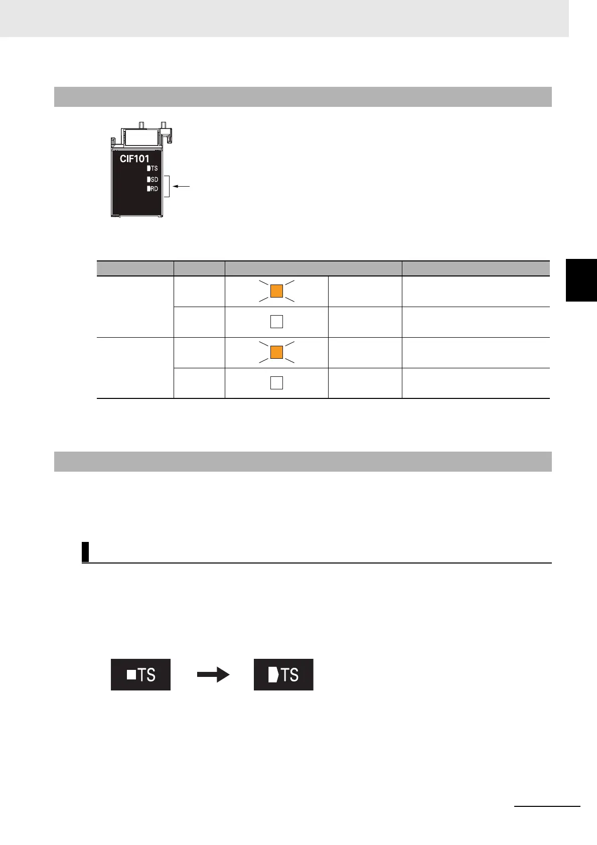
3-2-2 Send/Receive Indicators
The following table lists the possible states for these indicators and what they mean.
The appearance of the indicators has been changed for NX-CIF210 with lot numbers that represent the
date
of or after September 20, 2018. In addition, the appearance of the indicators has been changed for
NX-CIF101 and NX-CIF105 with lot numbers that represent the date of or after March 20, 2019. See
below for details on the change.
Shape Change of Light Emitting Part
NX-CIF101, NX-CIF105, and NX-CIF210 are applicable.
The shape of the light emitting part of each indi
cator has been changed from a square to a penta-
gon.
Below is an example of the TS indicator.
3-2-2 Send/Receive Indicators
Indicator
*1
*1. The NX-CIF210 has the following four indicators: SD1, RD1, SD2, and RD2. The SD1 and RD1 indicators
show the send and receive status for port 1. The SD2 and RD2 indicators show the send and receive status
for port 2.
Color Status Send/receive status
SD Yellow Lit Sending data
--- Not lit Waiting to send data
RD Yellow Lit Receiving data
--- Not lit Waiting to receive data
3-2-3 Appearance Change of the Indicators
Change Details
These indicators show the communications
status with the serial communications device.
Before change After change
 Loading...