A - 19
Appendices
NX-series Communications Interface Units User’s Manual (W540)
A-3 List of NX Objects
A
A-3-3 NX Objects for the NX-CIF210
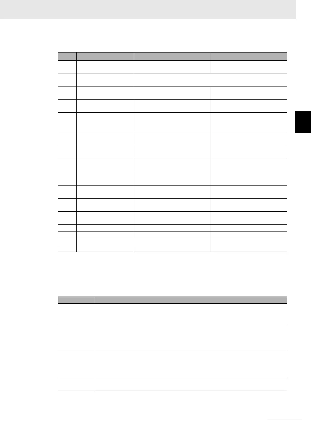
• The following table shows the Port Status. You can access this data as WORD data or BOOL data.
• The following table shows the Input Data Type. You can access this data as WORD d
ata or BOOL
data.
Bit
Status name
*1
*1. “n” in “Chn” is the port number.
Condition to change to TRUE Condition to change to FALSE
0 Chn Send Data Exist Send buffer contains one or more
bytes of data.
Send buffer contains 0 bytes of
data.
1 Chn Send Completed
Togg
le Bit
The value alternates between TRUE and FALSE each time a transmis-
sion is completed.
2 Chn Send Buffer Full
Flag
Send buffer contains 4,097 or
more bytes of data.
Send buffer contains 511 or fewer
bytes of data.
3 Chn Receive Buffer Full
Flag
Receive buffer contains 4,097 or
more bytes of data.
Receive buffer contains 511 or
fewer bytes of data.
4 Chn RS Signal Receive buffer contains 4,097 or
more byte
s of data. Or, the RS Sig-
nal ON command is executed.
Receive buffer contains 511 or
f
ewer bytes of data. Or, the RS
Signal OFF command is executed.
5 Chn CS Signal The remote node is busy. The remote node is waiting to
receive data.
6 Chn ER Signal The ER Signal ON command is
ex
ecuted.
The ER Signal OFF command is
executed.
7 Chn DR Signal The remote node turned ON the
DR signal.
The remote node turned OFF the
DR signal.
8 Chn Remote Unit Com-
munications Status
*2
*2. This status bit is valid when RS/CS or Xon/Xoff flow control is performed.
The remote node is busy. The remote node is waiting to
receive data.
9 Chn Local Unit Commu-
nications Status
Receive buffer contains 4,097 or
more bytes of
data.
Rece
ive buffer contains 511 or
fewer bytes of data.
10 Chn Line Monitoring Flag The serial line monitor is operat-
ing.
The serial line monitor is stopped.
11 Chn Receive Data Exist Receive buffer contains 1 or more
byte
s of data.
Receive buffer contains 0 bytes of
data.
12 Chn Parity Error A parity error occurs. The parity error is cleared.
13 Chn Framing Error A framing error occurs. The framing error is cleared.
14 Chn Overrun Error An overrun error occurs. The overrun error is cleared.
15 Chn End Detected An end is detected. An end is not detected.
Bits Description
15
Indicates whether there is an error in the receive data.
*1
0 hex: There are no errors.
1 hex: There is an error
*1. This bit indicates a parity error, framing error, or overrun error that occurred when data was received from
the serial communications device.
12 to 14 Indicates whether there is data received by the CIF Unit from the serial line.
0 hex: No data received, and the end not detected.
1 hex: Data received, and
the en
d not detected.
2 hex: The end detected. Whether there is data received depends on cases.
*2*3
08 to 11 Indicates whether there is a response from the CIF Unit to the control command sent from
the CPU Unit or communications master to the CIF Unit.
*4
0 hex: No response
2 hex: Response
00 to 07
*5
Indicates the command code of the control command that the CPU Unit or communications
master sent to the CIF Unit.
 Loading...