4 Installation and Wiring
4 - 22
NX-series Communications Interface Units User’s Manual (W540)
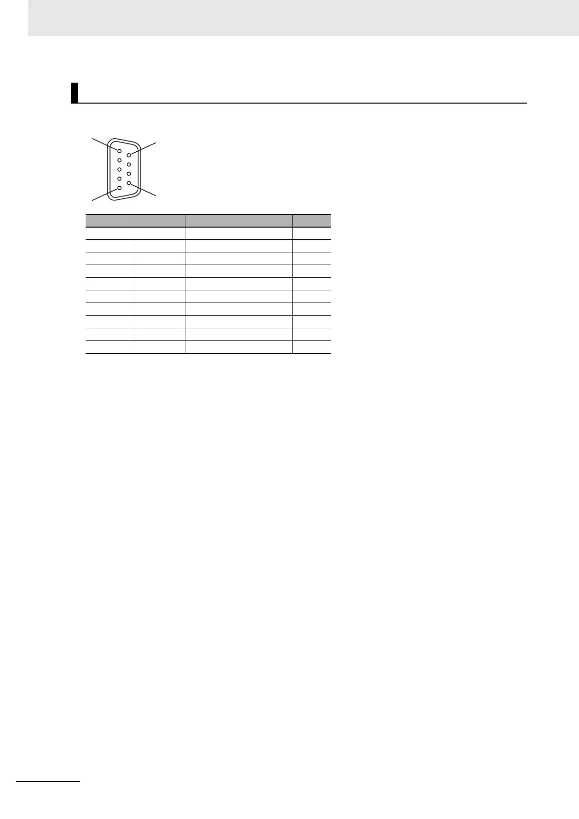
The arrangement of the D-sub connector pins on the NX-CIF210 are given in the following table.
Arrangement of D-sub Connector Pins on NX-CIF210
Pin No. Abbrev. Signal name I/O
1 --- Not used. ---
2 RD Receive data Input
3 SD Send data Output
4 ER Data terminal ready Output
5 SG Signal ground ---
6 DR Data set ready Input
7 RS Request to send Output
8 CS Clear to send Input
9 --- Not used. ---
Shell SHLD Shield ---
 Loading...