61
8
8 bk97
1
2 4 53
(for VHS)
(for VHS)
(for HDD/DVD)
(for HDD/DVD)
1
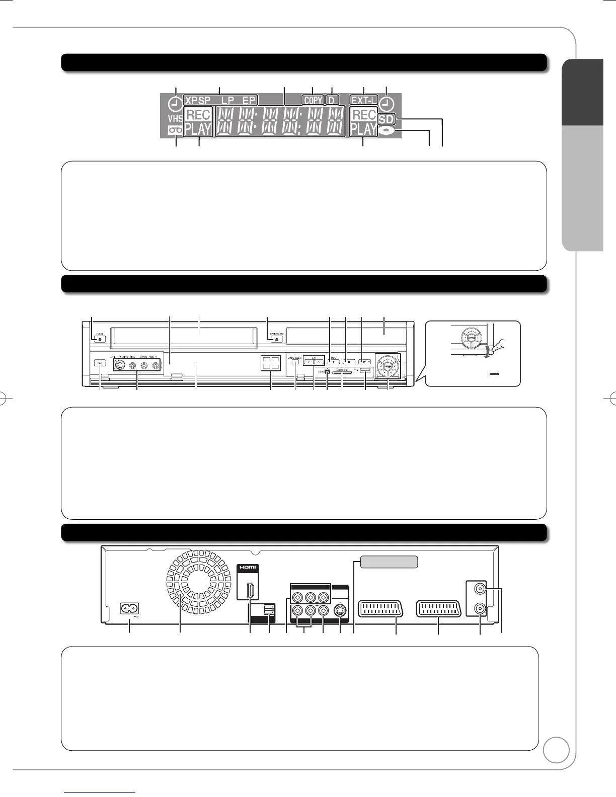
Timer recording indicator (
z
) ................... (➔ 22
)
On:
When a timer recording programme is registered and a
recordable disc or video cassette is inserted.
Flashes:
When the unit cannot record a timer recording programme (e.g.,
there is no disc
or video cassette
, etc.).
2
Recording mode indicator ........................ (➔ 21
)
3
Main display
4
Copying indicator
5
Digital broadcast indicator
Lights when the unit is receiving digital broadcast or GUIDE
Plus+ data.
6
Linked timer recordings with external
equipment indicator .................................. (➔ 31)
7
Tape indicator
8
Operation status
9
Disc indicator
bk
SD card slot indicator
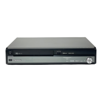
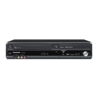
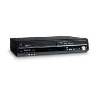
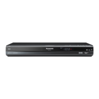
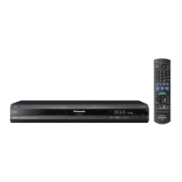
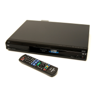
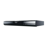
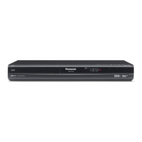
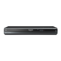
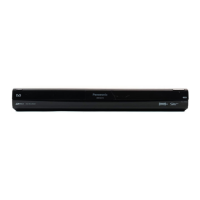
Main Unit
DVD
VHS
HDD
SD
1 2
6 97
3 4 5
bk8 bobl bm bn
Opening the front panel
Press down on the
part
with your finger.
Disc tray
The unit’s display
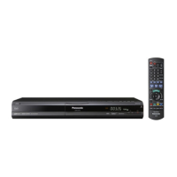
Remote control
signal sensor
Cassette
compartment
1
Cassette eject button ....................................(➔ 89)
2
Disc tray open/close button ....................(➔ 20, 89)
3
Start recording button ...................................(➔ 21)
4
Stop button .............................................(➔ 20, 21)
5
Play/✕1.3 button ...........................................(➔ 20)
6
Standby/on switch (
^
/I) .............................(➔ 13)
Press to switch the unit from on to standby mode
or vice versa. In standby mode, the unit is still
consuming a small amount of power.
7
AV3 input terminals .......................................(➔ 32)
8
HDD/DVD/SD/VHS drive indicator ...............(➔ 20)
• Lights when the HDD, DVD, SD or VHS drive is selected.
9
DRIVE SELECT button ................... (➔ 20, 21, 44)
• Drive changes each time you press [DRIVE SELECT].
bk
Channel Select button ..................................(➔ 21)
bl
DV IN terminal
(for a digital video camcorder) .....................(➔ 33)
bm
SD card slot ..................................................(➔ 89)
bn
USB port .......................................................(➔ 89)
bo
One Touch Copying operation button
...(➔ 23 to 25)
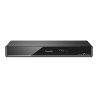
Rear Panel
AV OUT
AV 1 (TV)
RF
IN
RF
OUT
OUT
VIDEO
COMPONENT VIDEO OUT
R-AUDIO-L
S VIDEO
YP
B PR
AV 2 (EXT)
OPTICAL
DIGITAL AUDIO OUT
(
PCM/BITSTREAM
)
AC IN
DMR-EX98VEBK
PR0 00001010
SER NO.
465897
bn
312 bk bmbl
1
AC IN~ = Power supply
Connection for the AC mains lead
2
Cooling fan
3
HDMI AV OUT terminal .....................(➔ 12, 88)
Digital audio and video output terminal
4
Digital audio output terminal ....................(➔ 88)
5
COMPONENT VIDEO OUT (PROGRESSIVE/
INTERLACE) terminals ...........................(➔ 87)
Y = Luminance signal (brightness), P
B
= Chrominance signal
(colour difference), P
R
= Chrominance signal (colour difference)
6
AUDIO output terminals ....................(➔ 87, 88)
7
VIDEO output terminal ............................(➔ 87)
8
S VIDEO output terminal .........................(➔ 87)
9
Serial number
bk
AV2 (EXT) 21-pin Scart terminal .......(➔ 11, 86)
Connection of an external unit
bl
AV1 (TV) 21-pin Scart terminal ...(➔ 10, 11, 86)
TV set connection
bm
Aerial output terminal ..................(➔ 10, 11, 86)
bn
Aerial input terminal ....................(➔ 10, 11, 86)
For information about the 21-pin Scart terminal (➔ 10)
Quick Start Guide
STEP 1
RQT9089-BDMR-EX98VEB.indb9RQT9089-BDMR-EX98VEB.indb9 2008/04/2318:59:122008/04/2318:59:12
 Loading...