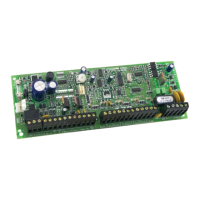
LOCATION AND MOUNTING
The printed circuit board, mounting hardware and keypad should be removed from the packaging inside
the panel box. Press the five white nylon mounting studs into cabinet from the back prior to mount-
ing the cabinet. Before mounting the circuit board on the back of the cabinet, pull all cables into cabinet
and prepare them for connection.
Be sure to select a control panel installation site that is not easily accessible to intruders. Leave at least
2” around the panel box to permit adequate ventilation/heat dissipation. Installation location should be
dry, close to an AC source, ground connection and a telephone line connection.
EARTH GROUND
The earth terminal should be connected to the cabinet and grounding rod as per local electrical codes.
AC
Use a 16VAC transformer with a minimum 40VA rating to provide sufficient AC power (for
748ES
, use
75VA). Do not utilize any switch-controlled outlets to power the transformer. UL listed systems require
K12 model T16V40 transformer; ULC listed systems require Frost model FTC1637 transformer.
PROGRAMMABLE OUTPUTS
If the programmable outputs are to be used, they should ideally be connected through external relays, as
these outputs should not drive more than 30mA. A relay should be used in cases where more than 30mA
is required.
BELL/SIREN OUTPUT
Bells or other warning devices requiring a steady voltage output during alarms, are powered by the Bell+/
Bell- terminals. The bell output is microprocessor-controlled and will automatically shut down if current
exceeds 3 amps. The processor will allow current to resume only after the bell cut-off time expires.The
correct polarity connections should be made when hooking up sirens (speakers with built-in siren dri-
vers). “Bell+” terminal is the connection for the positive lead. “Bell-” terminal is the connection for the neg-
ative lead. The bell output supplies 12V upon alarm. It can support two 20-watt or two 30-watt sirens.
(Above 1A, battery supplies current.)
AUXILIARY POWER TERMINALS
Motion detectors and any security devices requiring 12VDC voltage can be powered by the auxiliary
power supply. A maximum of 400mA 12VDC is available, (225mA for 748ES and 250mA max. for 24 hr.
standby-UL, ULC installations) from the AUX+ and AUX- terminals. For each additional keypad or PS1
module, the auxiliary current supply must be reduced by individual model current consumption. The auxil-
iary supply is microprocessor-protected against current overload and automatically shuts down if current
exceeds 1 amp. Auxiliary power will resume after battery test takes place, (within 0 - 60 seconds).
ZONE INPUT TERMINALS
(Please refer to zone connections (page 9) and wiring diagram in "Programming Guide".)
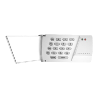
KEYPAD CONNECTIONS
The keypad has a terminal strip with 6 connections. The first 4 connections are labeled "yellow", "green",
"black" and "red". They are connected to the corresponding color terminals on the control panel board.
The last 2 connections are labeled " zone” and “COM". This is the zone input on the keypad. A green (1K
ohm) resistor must be used on this zone. If the zone input is not used, the green (1K ohm) resistor must
be installed on the terminal strip. The zone information is carried to the panel on the 4 wires of the key-
pad connection. Up to 5 keypads may be used on a system with 2 of the keypads utilizing the zone input.
Displayed as
718/728L/728 738/748/748ES
Keypad zone 1 Zone 7 (Partition B) Zone 13 (Partition A)
Keypad zone 2 Zone 8 (Partition B) Zone 19 (Partition B)
Jumper "off" - Keypad zone 1 activated.
Jumper "on" - Keypad zone 2 activated.
(Panel default jumper setting is "on" (keypad zone 2). To switch to keypad zone 1, a "keypad power
down" must be conducted. To do so, all 4 wires must be disconnected.)
8
IM8
 Loading...