PROGRAMMABLE OUTPUT (PGM) TYPE AND OPTIONS
Program type (Address 195) SECTION 33
Each PGM output can be programmed as normally open (N.O.) or normally closed (N.C.).
Regular N.O. - solid state switch momentarily conducts to negative (30mA) upon an event or events.
Regular N.C. - solid state switch momentarily opens circuits from ground upon an event or events.
Timed N.O. or N.C. - solid state switch changes state for the amount time programmed in address 254
upon event or events (see special timing functions page 20).
"OR", "AND", "EQUAL"
Each PGM output can operate upon one event or multiple events. In the case of the latter, the output can
be programmed to operate when the events are logically:
"OR" Event 1 or Event 2 (example: key [1] OR [4] on keypad)
"AND" Event 1 and Event 2 (example: keys [1] AND [4] on keypad - not limited to events specified))
"EQUAL" Event 1 exactly equals Event 2 (limited to the events specified)
Typical PGM (Programmable Output) programming
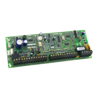
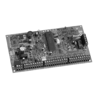
PGM 1 addresses: 196__/__198__/__ PGM 2 addresses: 197__/__199__/__ (
738
,
748
,
748ES
)
Note: For other PGM operations, i.e. home automation, programmable controller, false alarm reduction,
etc., use
Espload
software to provide programming codes (over 1000 options available). (If other
programming options are needed, fax requests to technical support department at 514-491-2313.)
SYSTEM OPTIONS (Default = "off" for addresses 200-242)
Code priority (Addresses 200 to 204)
Key [1] represents user code 1, [2] = 2, [3] = 3, [4]= 4, [5] = 5, [6] = 6, [7] = 7, [8]= 8, [9]=9,
[10]= 10, [11] = 11, [12] = 12, [BYP] = 13, [MEM] = 14, [TRBL] = 15, and key [2ND] = 16.
If partitioning is disabled (Address 206, key [8] "off")
Address 200: Lighted keys indicate which user codes can activate "stay" arming.
Address 202: Lighted keys indicate which user codes can activate "auto bypass (away)" arming.
Address 204: Lighted keys indicate which user codes can "bypass" zones.
25
IM8
FUNCTION DESCRIPTION TYPE HEXA PROG.
Address Address
196/197 198/199
Ground start Pulse Provides 3 sec. pulse before 5 5/2 [2ND]/8
(Timed N.O.) communication attempt.
Push key [1] and [2] Provides output when keys [1] 1 5/8 [2
ND]/6
(Regular N.O.) and [2] are pressed simultaneously.
System armed Output removed when system 9 2/B [2
ND]/8
(Regular N.C.) armed.
Strobe output Provides latching output on 1 2/C [2
ND]/2
(Regular N.O.) alarm, until disarmed.
Fail to communicate Provides output upon fail to 5 2/6 [2
ND]/4
(Timed N.O.) communicate for
2 minutes.
2nd telephone line relay Provides output after one failed [2
ND] 7/A [2ND]/E
(Regular N.O.) communication attempt.
Kiss off Provides
3 sec. output after signal 5 7/D [2ND]/8
(Timed N.O.) received at monitoring station.
Time output Provides
3 sec. output every day 6 2/3 1/4
(Timed N.O.) at 8PM.
Fire reset ([
TRBL] + [11])[BYP] 5/3 2/[2ND]
(Timed N.C.)
Provides 4 sec. to reset detectors after alarm
*Times must be programmed at address 254.
**Not permitted on UL listed systems.
*
*
*
*
*
**