75
CONEXIÓN DE LAS SEÑALES
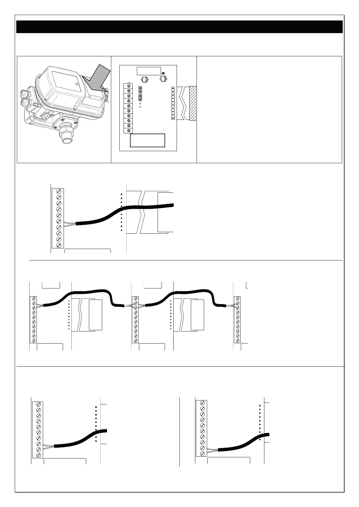
Tarjeta de expansión: está situada en la parte posterior del inversor (véase fig. de
abajo)
1
2
3
4
5
6
7
8
9
10
J P3
J P4
J P5
Descripción de la función de los terminales:
10: no conectado
9: RS 485 +
8: RS 485 -
7: no conectado
6: no conectado
5: entrada nivel
4: GND
3: salida señal NC
2: común C
1: salida señal NO
JP3: comunicación standard con 2 / 4 cables
JP4: comunicación standard con 2 / 4 cables
JP5: resistencia de carga para largas distancias (> 10 m
)
- CONEXIÓN DE LA
SEÑAL DE NIVEL
10
9
8
7
6
5
4
3
2
1
(u otra señal de entrada)
Conectar el cable de señal a los
terminales 4 y 5. En las aplicaciones
con inversor en paralelo, el cableado
deberá efectuarse en el inversor
MASTER
- CONEXIÓN DE LA
SEÑAL ENTRE LOS INVERSORES
(RS485)
10
9
8
7
6
5
4
3
2
1
10
9
8
7
6
5
4
3
2
1
10
9
8
7
6
5
4
3
2
1
conectar entre sí
los terminales 8 de los
distintos inversores (RS
485 –)
los terminales 9 de los
distintos inversores (RS
485 +)
como se muestra al lado
- CONEXIÓN DE LA
SEÑAL DE ALARMA
(en las aplicaciones con inversor en paralelo, el cableado deberá efectuarse en el inversor MASTER)
10
9
8
7
6
5
4
3
2
1
Lógica NC
(normalmente
cerrado)
Conectar el cable
de señal a los
terminales 2 y 3
10
9
8
7
6
5
4
3
2
1
Lógica NO
(normalmente
abierto).
Conectar el
cable de señal
a los terminales
1 y 2
La carga maxima conectable es 2 A a 250 Vac
 Loading...